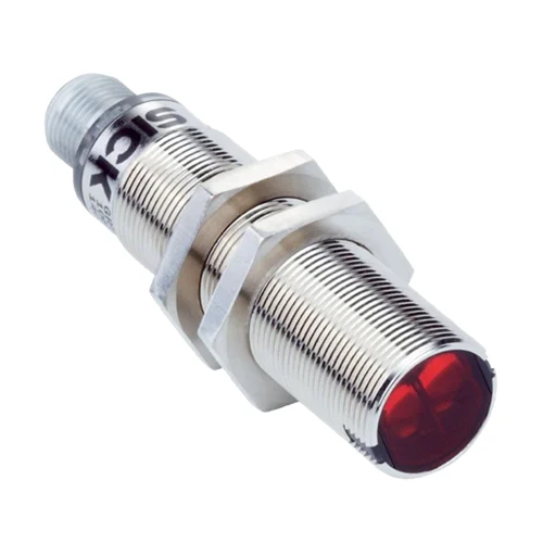
SICK 1067985 GRSE18-N2442 NPN Through-beam Sensor Pair

USD 87.62

GRSE18-N2442 provides 0–10 m red-light through-beam sensing, NPN complementary outputs, 1,000 Hz switching, a sender test input and M12 connectors.

SKU SICK-1067985 Category
SICK GR18

SICK GRSE18-N2442 NPN Through-beam Sensor Pair

BrandSICK
Model IdentifierGRSE18-N2442
Official Part Number1067985

Technical Overview

The SICK GRSE18-N2442 is a through-beam photoelectric sensor pair with separate sender and receiver units. Its 650 nm red PinPoint LED provides a 0–10 m sensing range and 0–15 m maximum range, with a 250 mm spot at 10 m. A 270° potentiometer adjusts receiver sensitivity, and complementary NPN outputs provide light and dark switching states. Response is <500 µs with resistive load, with 1,000 Hz switching at a 1:1 light/dark ratio. Both units use M12 four-pin connectors, and the sender test input switches emission off at 0 V. The M18 × 1 nickel-plated brass/ABS housings provide axial optics and IP67 protection; output current derates to 50 mA above 24 V or +49 °C.

Red PinPoint through-beam sensor pair with 0–10 m sensing, NPN switching, 1,000 Hz operation, sender test input and M12 four-pin connectors.

Key Features

  • Through-beam sender/receiver pair; 0–10 m sensing and 0–15 m maximum range
  • 650 nm visible red PinPoint LED; Ø250 mm at 10 m
  • 270° sensitivity potentiometer
  • NPN complementary light/dark outputs
  • <500 µs response with resistive load; 1,000 Hz at 1:1 light/dark ratio
  • M12 four-pin male connectors on sender and receiver
  • Sender test input: 0 V switches emission off
  • 10–30 V DC; output current ≤100 mA; maximum 50 mA above 24 V supply or +49 °C ambient
  • Axial M18 × 1 nickel-plated brass/ABS housing; PMMA optics
  • IP67; green power and yellow received-light indicators

Detect opaque material by interrupting a separate red sender-to-receiver beam and command sender-off checks through the dedicated test input.

Technical Specification Matrix

ParameterValue
Functional principleThrough-beam photoelectric sensor; separate sender and receiver
Sensing range0–10 m
Maximum sensing range0–15 m
Light sourceVisible red PinPoint LED; 650 nm
Average LED service life100,000 h at ambient +25 °C
Light spot sizeØ250 mm at 10 m
Adjustment270° sensitivity potentiometer
Switching outputNPN complementary Q and Q̅ outputs
Switching modeLight/dark switching; complementary outputs
Output current≤100 mA; maximum 50 mA when supply >24 V or ambient temperature >49 °C
Response time<500 µs signal transit time with resistive load
Switching frequency1,000 Hz at 1:1 light/dark ratio
Power supply10–30 V DC; short-circuit-protected network, maximum 8 A
Ripple<5 Vpp; remain within supply-voltage tolerances
ConnectionM12 four-pin male connector on sender and receiver
Sender pin assignmentCD-072: 1 BN=L+; 2 WH=not connected; 3 BU=M; 4 BK=Test
Receiver pin assignmentCD-072: 1 BN=L+; 2 WH=Q̅; 3 BU=M; 4 BK=Q
Test inputSender OFF when Test is at 0 V
Circuit protectionSupply reverse-polarity protection; inputs and output reverse-polarity protection; output overcurrent and short-circuit protection
Protection classIII
IP ratingIP67
IndicatorsGreen continuously on: power on; yellow received-light indicator on: object absent, off: object present
Operating temperature−25 to +55 °C at supply ≤24 V and output current <50 mA
Storage temperature−40 to +70 °C
EMCEN 60947-5-2
Individual components2072237 GRS18-D2441 sender; 2073766 GRE18-N2432 receiver
Current consumption30 mA
NPN signal voltage HIGH/LOWHIGH approximately supply voltage; LOW ≤3 V
Housing designCylindrical; axial optical axis; M18 × 1 mounting thread
Axial extent73.5 mm including integral M12 connector, manufacturer drawing
Housing materialNickel-plated brass and ABS
Optics materialPMMA
Items suppliedFour metal fastening nuts; drawing shows two per unit, 24 mm across flats
UL fileE348498

Industrial Applications

1. Counting separated opaque cartons across a conveyor

A conveyor can place the separate sender and receiver on opposite sides of a path carrying spaced opaque cartons. Each carton interrupts the red beam and creates an NPN transition for an external counter. The 0–10 m sensing range supplies the installed-separation basis, while the 1,000 Hz rating and resistive-load response establish timing limits for distinct carton passages.

Problem Solved

Beam interruption provides external counting logic with carton-passage events without relying on light reflected from carton surfaces, supporting tracking of separated loads across the conveyor.

Carton counting 0–10 m 1,000 Hz

2. Monitoring continuity of an opaque material feed

A sheet feeder can align the beam across the expected path of an opaque strip so that normal material blocks transmission. A break or exhausted roll exposes the receiver to the sender. External process logic evaluates this received-light change over time; commissioning establishes material opacity and installed geometry, using the sensitivity potentiometer to set reception.

Problem Solved

A sustained change in beam reception gives external feeder logic a material-loss reference, helping identify an interrupted strip before processing continues with the expected material absent.

Material continuity Opaque strip Received-light change

3. Checking the optical signal chain during a controlled test

A maintenance sequence can hold the optical path clear and command the sender Test input to 0 V, which switches emission off. External diagnostic logic observes the resulting receiver output change, then restores the normal sender condition. M12 four-pin connections provide the documented Test and output functions; this is a controlled process diagnostic rather than a safety-rated test.

Problem Solved

A commanded sender-off event gives external diagnostic logic a known optical stimulus, helping distinguish an unchanging receiver signal from the expected beam-reception response during maintenance.

Sender-off test 0 V Test input Process diagnosis

Select your currency