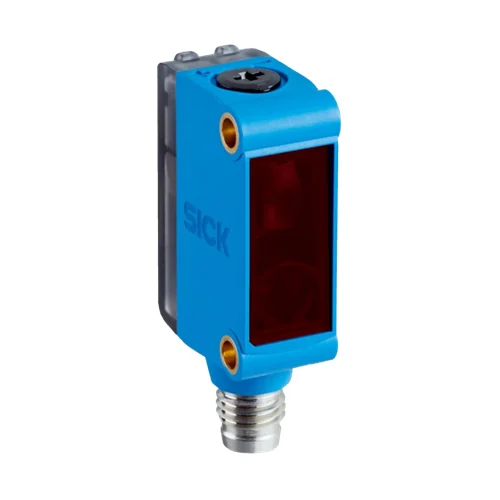
SICK 1101441 GTB6-F4211 PNP Background-Suppression Sensor

USD 70.72

Background suppression with 35–140 mm sensing, a five-turn spindle, complementary PNP outputs, 1,000 Hz switching, M8 connection and IP67 housing.

SKU SICK-1101441 Category
SICK G6

SICK GTB6-F4211 PNP Background-Suppression Sensor

BrandSICK
Model IdentifierGTB6-F4211
Official Part Number1101441

Technical Overview

The SICK GTB6-F4211 is a background-suppression photoelectric proximity sensor with a 35–140 mm sensing range and a 5–250 mm maximum range on 90% remission reference white. Its 650 nm visible red PinPoint LED forms a 6 mm spot at 100 mm, and a five-turn mechanical spindle sets the sensing condition. Complementary PNP outputs support light/dark switching through a rotary selector. Response is below 625 µs with a resistive load, with 1,000 Hz switching at a 1:1 light/dark ratio. The rectangular ABS/PC housing has a PMMA front screen, M3 mounting holes and an M8 four-pin plug. IP67 protection and 10–30 V DC operation support machine integration, with output current limited to 50 mA above 24 V.

35–140 mm background-suppression sensor with five-turn adjustment, complementary PNP outputs, 1,000 Hz switching and M8 four-pin connection.

Key Features

  • Background-suppression sensing; 35–140 mm sensing range
  • Maximum reference-white range 5–250 mm; 90% remission
  • 650 nm visible red PinPoint LED; Ø6 mm spot at 100 mm
  • Five-turn mechanical spindle for sensing adjustment
  • Complementary PNP outputs; light/dark rotary selector
  • Response <625 µs with resistive load; 1,000 Hz at 1:1 light/dark ratio
  • 10–30 V DC; 30 mA without load; output ≤100 mA, or 50 mA above 24 V
  • M8 four-pin plug; M3 mounting holes
  • ABS/PC housing, PMMA front screen and IP67
  • Operating range −25 to +55 °C; temperature stability after adjustment ±10 °C

Set a target sensing zone with the five-turn spindle and deliver complementary PNP states to external inspection or counting logic.

Technical Specification Matrix

ParameterValue
Functional principlePhotoelectric proximity sensor with background suppression
Sensing range35–140 mm
Maximum sensing range5–250 mm on 90% remission reference white, DIN 5033
Reference-target rangesWhite 90%: 35–140 mm sensing, 5–250 mm maximum; gray 18%: 35–140 mm sensing, 7–200 mm maximum; black 6%: 35–140 mm sensing, 10–140 mm maximum
Light sourceVisible red PinPoint LED; 650 nm
Light spot sizeØ6 mm at 100 mm
Average LED service life100,000 h at TU=+25 °C
AdjustmentMechanical spindle, five turns
Digital outputComplementary PNP outputs
Switching modeLight/dark switching, selected through light/dark rotary selector
PNP signal HIGH/LOWHIGH = supply voltage minus ≤3 V; LOW approximately 0 V
Output current≤100 mA; maximum 50 mA at supply >24 V
Response time<625 µs signal transit time with resistive load
Switching frequency1,000 Hz at 1:1 light/dark ratio
Power supply10–30 V DC; limit values in short-circuit-protected network, maximum 8 A
Ripple±10%; remain within supply-voltage tolerances
Current consumption30 mA without load
Protection classIII
Circuit protectionSupply reverse-polarity protection; input/output reverse-polarity protection; output overcurrent and short-circuit protection
ConnectionM8 four-pin male connector
Pin assignmentCD-101: 1 BN=L+; 2 WH=Q; 3 BU=M; 4 BK=Q̅
Housing designRectangular
Housing materialABS/PC plastic
Front screen materialPMMA plastic
MountingM3 mounting holes
IndicationGreen LED: supply voltage active; yellow LED: received-light status
IP ratingIP67
Operating temperature−25 to +55 °C; temperature stability following adjustment ±10 °C
Storage temperature−40 to +70 °C
UL filesNRKH.E348498 and NRKH7.E348498
Physical Weight (kg)0.02

Industrial Applications

1. Checking a presented component against a distant background

An assembly fixture can present a component within the 35–140 mm sensing zone and set the background-suppression condition with the five-turn spindle. External inspection logic samples a PNP output after the part settles. Setup establishes the actual target and background separation using representative reflectance, while the M3 holes hold the selected optical position and the LED indicates received-light status.

Problem Solved

An adjusted target-zone condition gives external inspection logic a component-present reference, helping distinguish an omitted part from the expected settled assembly presentation.

Component inspection Background suppression Five-turn adjustment

2. Counting separated tabs on a moving carrier

A moving carrier can bring separated opaque tabs through the adjusted sensing zone and route PNP transitions to an external counter. The 1,000 Hz switching rating and response below 625 µs provide the sensor timing basis. Commissioning establishes tab coverage, spacing and input timing, with both the electrical load and the supply-dependent 50 mA limit respected when supply exceeds 24 V.

Problem Solved

Distinct tab-passage transitions give external counting logic a carrier-event reference, supporting cycle tracking through a compact sensor positioned on one side of the moving path.

Tab counting 1,000 Hz PNP transitions

3. Comparing complementary states during fixture diagnostics

A fixture can connect Q and complementary Q̅ to separate ordinary machine inputs while the sensor monitors normal part presentation. External maintenance logic compares the settled states with the expected complementary relationship and prompts inspection when they disagree. Sampling accounts for sensor response and input timing, while the actual pin assignment and load limits define the two connected signal paths.

Problem Solved

Complementary signal paths provide external maintenance logic with a consistency check on the reported optical condition and connected inputs, helping investigate an unexpected fixture indication.

Complementary signals Fixture diagnostics Two input paths

Select your currency