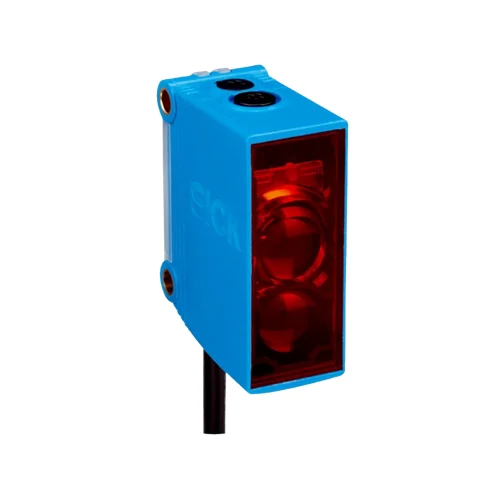
SICK 1065866 GTE10-P1212 PNP Diffuse Photoelectric Sensor

USD 54.08

GTE10-P1212 offers 40–950 mm reference-white sensing, 625 nm PinPoint LED, single PNP light/dark output, 1,000 Hz switching and a 2 m PVC cable.

SKU SICK-1065866 Category
SICK G10

SICK GTE10-P1212 PNP Diffuse Photoelectric Sensor

BrandSICK
Model IdentifierGTE10-P1212
Official Part Number1065866

Technical Overview

The SICK GTE10-P1212 is an energetic photoelectric proximity sensor with a 625 nm red PinPoint LED and a single PNP output. It detects reference-white targets over 40–950 mm, with a separately specified 20–1,300 mm maximum range; darker target ranges are shorter. A 270° potentiometer sets sensing range, and a separate light/dark selector adapts output behavior. Response is no greater than 500 µs with resistive load, with 1,000 Hz switching at a 1:1 light/dark ratio. The 10–30 V DC device uses a 2 m three-wire PVC cable, an IP67 ABS/PMMA plastic housing and a supplied BEF-G10DC01 mounting bracket. Green power and yellow received-light indicators support setup, with operation from −30 to +60 °C.

Energetic diffuse sensor with 40–950 mm reference-white range, red PinPoint LED, single PNP light/dark output, 2 m PVC cable and supplied mounting bracket.

Key Features

  • Energetic photoelectric proximity sensing from one mounting side
  • 40–950 mm sensing; 20–1,300 mm maximum on 90% reference white
  • 625 nm red PinPoint LED; Ø28 mm spot at 1,400 mm
  • 270° sensing-range potentiometer; separate light/dark selector
  • Single PNP output; current ≤100 mA
  • Response ≤500 µs with resistive load; 1,000 Hz at 1:1 light/dark ratio
  • 10–30 V DC; 20 mA current consumption; protection class III
  • 2 m three-wire PVC cable; 0.14 mm² conductors
  • ABS/PMMA plastic housing; IP67; −30 to +60 °C operation
  • BEF-G10DC01 mounting bracket supplied; green power and yellow received-light indicators

Adjust reflected-light detection from one mounting side and connect its PNP state to external process control, with the mounting bracket supplied.

Technical Specification Matrix

ParameterValue
Functional principleEnergetic photoelectric proximity sensing
Sensing range40–950 mm on 90% remission reference white, DIN 5033
Maximum sensing range20–1,300 mm on 90% remission reference white, DIN 5033
Other reference-target ranges18% gray: 60–400 mm sensing, 40–600 mm maximum; 6% black: 80–300 mm sensing, 60–450 mm maximum
Light sourceVisible red PinPoint LED; 625 nm
Average LED service life100,000 h at +25 °C
Light spot sizeØ28 mm at 1,400 mm
Additional spot sizesØ15 mm at 0.1 m; Ø19 mm at 0.5 m
AdjustmentSensing-range potentiometer, 270°
Switching outputSingle PNP
Switching modeLight/dark switching selected by separate light/dark selector
Output current≤100 mA
Response time≤500 µs signal transit time with resistive load
Switching frequency1,000 Hz at 1:1 light/dark ratio
Power supply10–30 V DC; short-circuit-protected network, maximum 8 A
Ripple<5 Vpp; remain within supply-voltage tolerances
Current consumption20 mA
Connection2 m three-wire PVC cable; do not bend below 0 °C
Conductor cross-section0.14 mm²
Conductor functionsCD-044: BN=L+; BU=M; BK=Q
Circuit protectionSupply and input/output reverse-polarity protection; interference suppression; output overcurrent and short-circuit protection
Protection classIII
Housing designRectangular
Housing materialABS/PMMA plastic
IP ratingIP67
Items suppliedBEF-G10DC01 mounting bracket
MountingØ4.2 mm holes; 36 mm hole spacing in drawing
IndicationGreen: power on; yellow: received-light-beam state
Operating temperature−30 to +60 °C
Storage temperature−40 to +70 °C
EMCEN 60947-5-2
UL fileNRKH.E348498 and NRKH7.E348498
Conditional UL325 complianceManufacturer specifies compliance when used with a sturdy protection hood, for example BEF-G10WSG, part 2071960; this hood is separate from the supplied mounting bracket
Physical Weight (kg)0.09

Industrial Applications

1. Confirming a part presented to a workstation

A workstation can place the sensor on one side of a presented part and use reflected red light to establish a presence condition for external sequence logic. The sensing-range potentiometer adapts the optical threshold to the installed gap. Setup checks the actual surface against the documented white, gray and black reference-target ranges so the configured condition corresponds to the intended part location.

Problem Solved

A reflected-light presence signal gives external sequencing a part-present reference, helping coordinate the next workstation step when the component reaches the checked position.

Workstation presence Adjustable range Single-sided sensing

2. Counting separated components in a feeder

A feeder can move separated components through the illuminated region and send PNP transitions to an external counter. The 1,000 Hz switching rating and response no greater than 500 µs provide timing references for the installed passage rate. Commissioning establishes target coverage, surface remission and spacing so each component produces a distinct event before the next reaches the sensing point.

Problem Solved

Discrete optical transitions give external counting electronics passage events, helping track separated components without placing a receiver or reflector on the opposite side of the feed.

Component count 1,000 Hz PNP output

3. Timing an occupied downstream receiving point

A transfer station can aim the sensor at a downstream receiving location where a component should remain only briefly. External control measures the detected-state duration and compares it with normal handoff timing. The light/dark selector sets the required PNP logic, and the received-light indicator provides setup feedback while the actual target and background geometry are established.

Problem Solved

A sustained detection state gives external transfer control an occupancy-duration reference, helping coordinate upstream release when a part remains at the downstream receiving point.

Transfer occupancy External timer Light/dark selection

Select your currency