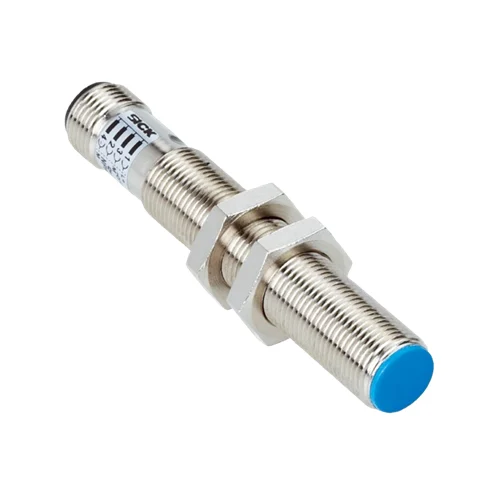
SICK 1017428 IM12-02BPS-ZCK PNP Inductive Proximity Sensor

USD 67.08

Flush M12 inductive sensing with a 2 mm nominal range, PNP normally-open output, 2,000 Hz switching and M12 four-pin male connector in an IP67 housing.

SKU SICK-1017428 Category
SICK IM Standard

SICK IM12-02BPS-ZCK PNP Inductive Proximity Sensor

BrandSICK
Model IdentifierIM12-02BPS-ZCK
Official Part Number1017428

Technical Overview

The SICK IM12-02BPS-ZCK is a short-body M12 × 1 inductive proximity sensor for flush installation in metal. It has a 2 mm nominal sensing range and a PNP normally-open output in a DC three-wire circuit, with a switching frequency of 2,000 Hz. The device operates from 10–30 V DC and connects through an M12 four-pin male connector. Its nickel-plated brass housing and plastic sensing face provide IP67 protection for operation from −25 to +75 °C. The output supports up to 300 mA continuous current, with a maximum 1.5 V voltage drop at maximum load. Availability after power-up is specified at no more than 2 ms.

Flush M12 PNP normally-open inductive sensor with 2 mm nominal sensing range, 2,000 Hz switching and M12 four-pin male connector.

Key Features

  • M12 × 1 short-body housing for flush installation in metal
  • 2 mm nominal inductive sensing range
  • PNP normally-open output; DC three-wire circuit
  • 2,000 Hz switching frequency
  • M12 four-pin male connector
  • 10–30 V DC; continuous output current ≤300 mA
  • Voltage drop ≤1.5 V at maximum load; availability delay ≤2 ms
  • Nickel-plated brass housing and plastic sensing face
  • Short-circuit and power-up pulse protection; wire-break protection
  • IP67; −25 to +75 °C operation

Install the M12 sensing face flush in metal and provide a PNP normally-open proximity signal to external fixture or motion-sequence control.

Technical Specification Matrix

ParameterValue
Functional principleInductive proximity sensing
Housing designMetric, short-body
Mounting threadM12 × 1
Body diameterØ12 mm
Nominal sensing range Sn2 mm
InstallationFlush in metal
Switching frequency2,000 Hz
Switching outputPNP, normally open (NO)
Electrical wiringDC three-wire
Power supply10–30 V DC
Ripple≤10% of VS
Voltage drop≤1.5 V at maximum Ia
Time before availability≤2 ms
Hysteresis1–10%
Reproducibility≤1% of Sr at constant supply voltage and ambient temperature
Temperature drift±10% of Sr
Continuous output current≤300 mA
ProtectionWire-break, short-circuit and power-up pulse protection
ConnectionM12 four-pin male connector
Pin assignment1 BN=L+; 4 BK=NO output; 3 BU=M; 2 not connected (CD-007)
Housing materialNickel-plated brass
Sensing facePlastic
IP ratingIP67; EN 60529
Operating temperature−25 to +75 °C
Maximum tightening torque7 Nm
Shock resistance30 g, 11 ms
Vibration resistance10–55 Hz, 1 mm
EMCEN 60947-5-2
Installation clearancesManufacturer diagram references A/B/C/D/E/F: 6 / 12 / 12 / 6 / 0 / 16 mm
Housing length45 mm
Thread length32 mm

Industrial Applications

1. Checking a metal part seated in an assembly fixture

An assembly fixture can present a metal component at a repeatable gap in front of the flush-mounted sensing face. The PNP normally-open output supplies a component-present condition for external inspection logic after the fixture settles. Commissioning verifies the actual material, target geometry and placement tolerance against the 2 mm nominal sensing range, rather than treating nominal range as an assured installation distance.

Problem Solved

A metal-present reference helps external inspection logic identify an empty or mispresented fixture location before the next assembly operation proceeds at the station.

Fixture seating Flush mounting PNP normally open

2. Counting metal teeth for rotational-speed monitoring

A rotating mechanism can present separated metal teeth or flags past the sensor at a controlled gap. External counting logic derives rotational speed from the pulse frequency and the known number of targets per revolution. Tooth spacing, material and transit speed are assessed against the 2 mm nominal range and 2,000 Hz switching specification during commissioning.

Problem Solved

Repeated metal-target transitions give an external counter a rotation-rate reference, helping the machine monitor shaft motion using the known number of teeth or flags.

Tooth passage External speed calculation 2,000 Hz

3. Timing an actuator’s arrival at the end of a stroke

An actuator can carry a metal flag that enters the sensor’s range when the mechanism reaches its process end position. External timing logic starts from the motion command and stops at the PNP arrival transition, comparing elapsed travel time with configured limits. Setup checks flag material, gap and repeatability, and begins timing only after the sensor’s documented power-up availability interval.

Problem Solved

A discrete arrival event lets external timing logic compare stroke duration with the expected process interval, helping identify delayed motion at the monitored end position.

Stroke timing Metal arrival flag External timer

Select your currency