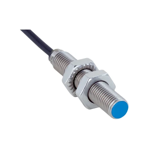
SICK 1089658 IMB08-02BPSVU5S M8 PNP IO-Link Inductive Sensor

USD 54.08

Flush M8 inductive sensor with 2 mm nominal range, PNP normally-open output, IO-Link V1.0, visual adjustment indicator, IP68/IP69K and 5 m PUR cable.

SKU SICK-1089658 Category
SICK IMB

SICK IMB08-02BPSVU5S M8 PNP IO-Link Inductive Sensor

BrandSICK
Model IdentifierIMB08-02BPSVU5S
Official Part Number1089658

Technical Overview

The SICK IMB08-02BPSVU5S is a standard-design M8 ×1 inductive proximity sensor for flush installation. Nominal sensing range is 2 mm and assured range is 1.62 mm, with reference reduction factors for different target metals. Its PNP normally-open output switches at up to 4,000 Hz, while IO-Link V1.0 reports whether Sr and Sa have been reached. A visual adjustment indicator supports local gap setup. The 10–30 V DC device connects through a 5 m three-wire PUR cable with 0.14 mm² conductors. A V2A stainless steel housing and LCP sensing face provide IP68/IP69K protection and coolant-lubricant resistance, with operation from −40 to +100 °C. Two toothed V2A mounting nuts are supplied.

Flush M8 PNP normally-open inductive sensor with 2 mm nominal range, IO-Link V1.0, visual adjustment indicator and 5 m PUR cable.

Key Features

  • Standard-design M8 ×1 inductive sensor for flush installation
  • 2 mm nominal range; 1.62 mm assured range
  • PNP normally-open output; 4,000 Hz switching frequency
  • IO-Link V1.0, COM2, 38.4 kBaud
  • One-byte process data reports Sr-reached and Sa-reached states
  • Visual adjustment indicator for local target-gap setup
  • 5 m three-wire PUR cable; 0.14 mm² conductors; 3 mm diameter
  • V2A stainless steel housing; LCP sensing face; IP68/IP69K
  • 10–30 V DC; ≤200 mA continuous current; short-circuit and power-up pulse protection
  • −40 to +100 °C operation; coolant-lubricant resistance; two toothed V2A fastening nuts

Use local adjustment indication and IO-Link range states to establish a metal-target gap while providing a PNP normally-open condition to external control.

Technical Specification Matrix

ParameterValue
Functional principleInductive proximity detection
Housing designMetric standard design
Mounting threadM8 ×1
Body diameter8 mm
InstallationFlush
Nominal sensing range Sn2 mm
Assured sensing range Sa1.62 mm
Digital outputPNP normally open, DC three-wire
Switching frequency4,000 Hz
Connection5 m three-wire PUR cable
Conductor cross-section0.14 mm²
Cable diameter3 mm
Conductor functionsCD-452: BN=L+; BU=M; BK=NO output / IO-Link C
Communication interfaceIO-Link V1.0, COM2, 38.4 kBaud
Process dataOne byte: bit 0=Sr reached; bit 1=Sa reached
Visual adjustmentVisual adjustment indicator; diagram relates switching output and LED to Sr and Sa =0.81 Sn
Power supply10–30 V DC
Ripple≤10%
Voltage drop≤2 V at maximum output current
Hysteresis3–20%
Reproducibility≤2% of Sr with constant supply and ambient temperature
Temperature drift±10% of Sr
Continuous current≤200 mA
No-load current≤10 mA
Circuit protectionShort-circuit and power-up pulse protection
Protection classIII
Housing materialV2A stainless steel, DIN 1.4305 / AISI 303
Sensing-face materialLCP plastic
IP ratingIP68 to EN 60529; IP69K to ISO 20653:2013-03
Operating temperature−40 to +100 °C
Manufacturer application areasCoolant/lubricant zones; mobile machines; difficult application conditions
Special propertiesCoolant-lubricant resistance; visual adjustment indicator; temperature resistance
Housing length45 mm
Thread length41 mm
Items suppliedTwo V2A stainless steel fastening nuts with locking teeth; 13 mm across flats
Tightening torqueTypical 7 Nm using non-toothed nut side; typical 14 Nm using toothed side
Shock and vibration resistance100 g / 11 ms / 1,000 cycles; 150 g / 1,000,000 cycles; 10–55 Hz, 1 mm; 55–500 Hz, 15 g
EMCEN 60947-5-2
UL fileE181493
MTTFD1,971 years
DCavg0%
Metal reduction factorsReference values, may vary: St37 steel 1; V2A/304 stainless approximately 0.74; aluminum approximately 0.43; copper approximately 0.33; brass approximately 0.46
Installation clearancesB=6.5 mm; C=8 mm; D=6 mm; F=16 mm, using manufacturer flush-installation diagram

Industrial Applications

1. Confirming a metal clamping slide in a coolant zone

A machine-tool fixture can bring a metal target on a clamping slide toward the flush sensing face and use the PNP normally-open state as an external sequence input. The stainless steel housing, LCP sensing face and documented coolant-lubricant resistance suit the stated environment. Setup evaluates the actual coolant and target material, preserves installation clearances and establishes the gap using the visual adjustment indicator.

Problem Solved

A noncontact metal-target condition gives external fixture logic a slide-position reference, helping coordinate the machining sequence with the presented mechanical position in the coolant zone.

Clamp-slide position Coolant resistance Visual adjustment

2. Counting separated metal features on a fast indexing mechanism

An indexing mechanism can present separated metal tabs to the sensor and route the PNP normally-open transitions to an external counter. The 4,000 Hz switching rating informs the available timing, while the installed gap remains within the assessed target range. Commissioning checks tab geometry, metal reduction factors and receiver response at the intended speed so that each feature produces a distinct event.

Problem Solved

Successive inductive target transitions give external counting logic index events, helping track repeated metal features without placing a contact switch against the rotating mechanism.

Metal-feature counting 4,000 Hz PNP NO

3. Reviewing target-gap states through IO-Link during setup

A commissioning station can connect the sensor to an IO-Link master and read the one-byte process data while moving a representative metal target toward the sensing face. Bit 0 reports Sr reached and bit 1 reports Sa reached, supplementing the local visual adjustment indication. The setup procedure relates those documented states to the required target position and records the observed result in external machine diagnostics.

Problem Solved

Separate reported range states give external setup diagnostics more information than one switching condition, helping verify that the target reaches the intended assured detection region.

IO-Link setup Sr/Sa states Target-gap verification

Select your currency