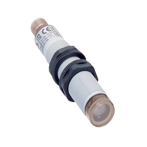
SICK 6034872 L21S-21KA1A M18 Safety Single-Beam Sender

USD 105.56

660 nm red LED sender with TE test input, straight M12 connection, PBT housing and IP67; separate L21 receiver and suitable external test device required.

SKU SICK-6034872 Category
SICK L21

SICK L21S-21KA1A M18 Safety Single-Beam Sender

BrandSICK
Model IdentifierL21S-21KA1A
Official Part Number6034872

Technical Overview

The SICK L21S-21KA1A is the plastic M18 axial sender for an L21 single-beam photoelectric safety switch. Its 660 nm visible red LED works with a separate L21E-21KA1A receiver, with a 16 m stated scanning range and a cold-temperature range condition. A TE input lets the suitable external test device switch the sender off to exercise the optical channel. Type 2, SIL 1, Category 2 and PL c characteristics apply only to the appropriate tested combination; system response includes the test device. The sender draws no more than 20 mA without load from a 19.2–28.8 V DC supply. Its PBT housing, glass front, straight M12 four-pin connector and IP67 protection support mounting, while an orange LED indicates emission.

M18 axial 660 nm red LED safety-switch sender with TE test input, straight M12 connection and IP67, requiring a separate receiver and suitable test device.

Key Features

  • L21S-21KA1A sender; separate matching L21E-21KA1A receiver
  • 660 nm visible red LED; one axial beam
  • 16 m stated range; manual specifies 10 m typical and 16 m maximum
  • TE test input: sender off below 5 V or open; on above 15 V
  • Type 2 / SIL 1 / Category 2 / PL c only with suitable external test device
  • System sensor response 0.2 ms plus test-device response
  • 24 V DC nominal, 19.2–28.8 V DC; ≤20 mA without load
  • Straight M12 four-pin connector; M18 × 1 PBT housing and glass front
  • Orange LED indicates sender emission; ±5° aperture angle
  • IP67; −40 to +55 °C operation with documented cold-range condition

Exercise the optical safety-switch channel through the sender TE input and a suitable external test device, with local indication of sender emission.

Technical Specification Matrix

ParameterValue
Product functionSender for L21 single-beam photoelectric safety switch; separate receiver and suitable external test device required
Scanning range16 m stated in exact datasheet; manual specifies 10 m typical and 16 m maximum for M18 axial pair
Cold-range conditionFor M18 axial optics, minimum scanning range reduces from 10 m at −20 °C to 7 m at −40 °C according to the manual curve
Number of beamsOne
Optical axisAxial
Optical wavelength660 nm system wavelength
Typical beam diameter12 mm for M18 system
Aperture / receiving angle±5° / ±5°
Response time0.2 ms system sensor response; total sensor/test-device response is 0.2 ms plus test-device response time
Protective-system requirementOnly with a suitable external Type 2 test device, such as an appropriately configured Flexi Classic or Flexi Soft
Safety typeType 2, IEC 61496-1; only with suitable test device
Safety integrity levelSIL 1, IEC 61508; only with suitable test device
Safety categoryCategory 2, EN ISO 13849; only with suitable test device
Performance levelPL c, EN ISO 13849; only with suitable test device
PFHD1.0 × 10⁻⁶ per hour, EN ISO 13849; only with suitable test device
Mission time20 years, EN ISO 13849
External test rate100/s maximum; must not be exceeded
Demand rate60/min maximum; at least 100 internal or external tests between two safety-response demands
ConnectionStraight M12 four-pin male connector
Pin assignment1 BN=L+; 2 WH=not connected; 3 BU=M; 4 BK=TE; sender has no receiver Q output
Power supply24 V DC nominal; 19.2–28.8 V DC at device; SELV/PELV; external supply buffers 20 ms mains interruptions
Supply installationShort-circuit-protected network, maximum 8 A; sender, receiver and test device share 0 V; reverse-polarity-protected supply connections
Residual ripple≤5 V peak-to-peak; stay within supply-voltage tolerances
Current consumption≤20 mA without load
Protection classIII, IEC 61140; reference voltage 50 V DC
HousingM18 × 1 cylindrical PBT plastic housing
Axial product length97.7 mm, including straight connector as drawn
Front screenGlass with PBT ring
Connector materialPBT
IP ratingIP67, EN 60529
Operating temperature−40 to +55 °C; cold-range curve applies
Storage temperature−40 to +75 °C
Relative humidity15–95%, non-condensing
Vibration resistance5 g, 10–55 Hz; IEC 60068-2-6
Shock resistance10 g, 16 ms; IEC 60068-2-27
Intended protective applicationsHazardous-area and access protection with suitable external test device; access must interrupt the beam; restart must be prevented while people remain inside
Detection limitsPeople outside the beam path are not detected; not for hand or finger protection
Installation conditionsRequired safety distance uses machine stopping time and entire protective-device response; avoid beam bypass, reflective-surface interference and mutual interference
InspectionSpecialist installation and commissioning; regular functional checks with an opaque test object at least 30 mm in diameter
Matching receiverL21E-21KA1A, part number 6034873; separate device
Light source660 nm visible red LED
Test input TESender off when TE <5 V or not connected; sender on when TE >15 V
Sender indicationOrange LED on=sender emitting; off=no supply or test mode
Physical Weight (kg)0.03

Industrial Applications

1. Providing the beam for a defined machine access opening

A machine access opening can mount this sender opposite the separate L21E-21KA1A receiver and connect both devices to the suitable external Type 2 test arrangement. Entry geometry forces access to interrupt the beam, while the protective system applies its required stopping distance and restart control. The optical path detects interruption rather than continued occupancy beyond the beam.

Problem Solved

A defined transmitted beam gives the tested protective system an access-interruption reference, supporting its stop function within the documented complete arrangement and detection limits.

Access beam Separate receiver External Type 2 testing

2. Exercising the optical channel during external testing

A suitable external test device can drive the sender’s TE input to stop emission and monitor the separate receiver’s Q response. This controlled optical interruption exercises the channel between tests of real access events. The system follows the documented maximum external test rate, at least 100 tests between safety-response demands and the response time of the complete test arrangement.

Problem Solved

Controlled changes in emission let the external protective system evaluate channel response, supporting fault detection through the documented sender, receiver and test-device combination.

TE input Optical channel test External monitoring

3. Checking sender emission during maintenance

Maintenance personnel can observe the orange sender LED while restoring an L21 optical path after wiring or mechanical work. An illuminated LED identifies sender emission, while an unlit LED corresponds to loss of supply or test mode. The separate receiver indication and the documented functional checks complete the channel assessment before the protective system returns to operation.

Problem Solved

Local emission indication helps maintenance distinguish the sender’s operating condition during channel restoration, supporting troubleshooting alongside the separate receiver and required protective-system checks.

Sender indication Emission check Channel maintenance
Select your currency