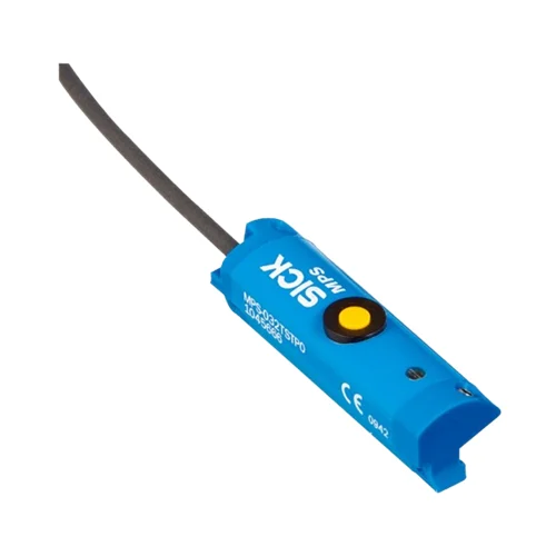
SICK 1062506 MPS-032TLTQ0 IO-Link Cylinder Position Sensor

USD 378.30

MPS-032TLTQ0 measures cylinder position over 32 mm with IO-Link V1.1 COM2, 16-bit position data, range teaching and a 0.3 m M12 cable.

SKU SICK-1062506 Category
SICK MPS-T

SICK MPS-032TLTQ0 IO-Link Cylinder Position Sensor

BrandSICK
Model IdentifierMPS-032TLTQ0
Official Part Number1062506

Technical Overview

The SICK MPS-032TLTQ0 is a magnetic cylinder-position sensor for T-slot mounting, with a 32 mm measuring range and 45 mm housing. IO-Link V1.1 COM2 sends a 16-bit position value with a 2.3 ms communication cycle; the data scale is 1/128 mm per count, separate from measurement accuracy. IO-Link provides measuring-range teach-in, range reset and key lock, while the local button resets the measuring range to factory settings. A 0.3 m PUR cable with M12 four-pin plug connects the device to its controller interface. The 15–30 V DC sensor uses a plastic IP67 housing, includes reverse-polarity and short-circuit protection, and operates from −20 to +70 °C.

32 mm T-slot cylinder-position sensor with IO-Link V1.1 COM2, 16-bit position data, measuring-range teaching and 0.3 m M12 cable.

Key Features

  • Magnetic cylinder-position measurement in a T-slot housing
  • 32 mm measuring range, specified ±1 mm; 45 mm housing length
  • IO-Link V1.1 COM2; 2.3 ms communication cycle
  • 16-bit position process data; scale 1/128 mm per count
  • IO-Link range teaching, range reset and key lock
  • 0.3 m PUR cable with M12 four-pin plug; axial cable outlet
  • 15–30 V DC; 25 mA consumption without load
  • Typical required magnetic field 4–30 mT; typical linearity error 0.3 mm at +25 °C
  • Reverse-polarity and short-circuit protection; status LED
  • Plastic housing; IP67 according to EN 60529; −20 to +70 °C operation

Send a digital cylinder-position value through IO-Link and configure the measuring range from the connected machine interface.

Technical Specification Matrix

ParameterValue
Functional principleMagnetic cylinder-position measurement
Cylinder typeT-slot
Cylinder types with adapterRound body; profile and tie-rod; dovetail groove cylinders; suitable adapter required
Measuring range32 mm, specified ±1 mm
Housing length45 mm
Power supply15–30 V DC
Current consumption25 mA without load
Protection classIII
Availability delay1.5 s
Magnetic field requirementTypically 4–30 mT
Typical linearity error0.3 mm at +25 °C; maximum deviation depends on response curve and minimum-deviation function
Circuit protectionReverse-polarity and short-circuit protection
Status indicatorLED
Connection0.3 m PUR cable with M12 four-pin plug
Electrical wiringDC four-wire
Cable outletAxial
Cable diameterØ2.6 mm
Conductor cross-section0.08 mm²
Bending radiusFixed installation >5× cable diameter; flexible use >10× cable diameter
Cable handlingDo not bend below 0 °C
Cable materialPUR
Housing materialPlastic
MountingSW1.5 fixing screws; 0.25–0.35 Nm tightening torque
Mounting screw spacing40 mm
IP ratingIP67 according to EN 60529
Operating temperature−20 to +70 °C
Shock resistance30 g, 11 ms
Vibration resistance10–55 Hz, 1 mm
EMCEN 60947-5-7
UL filesNRKH.E181493 and NRKH7.E181493
MTTFD489 years
DCavg0%
Mission time20 years
Output functionIO-Link
Communication interfaceIO-Link V1.1; COM2
IO-Link cycle time2.3 ms
Position process data16 bits; bits 0–15 contain position in units of 1/128 mm; data scale is not measurement accuracy
IO-Link adjustmentMeasuring-range teach-in, measuring-range reset and key lock
Local controlTeach-in button: reset measuring range to factory settings
IO-Link functionsStandard functions
Pin assignmentCD-179: 1 BN=L+; 3 BU=M; 4 BK=C communication; 2 WH not connected

Industrial Applications

1. Evaluating cylinder stop positions through digital position data

A cylinder-driven fixture can send its measured position through an IO-Link master to external machine logic. The controller compares the settled value with a commissioned process window within the 32 mm measuring range. The 16-bit position scale defines data interpretation, while the typical 0.3 mm linearity specification and actual cylinder mechanics determine appropriate acceptance bands.

Problem Solved

Digital position data gives external fixture logic a process-window reference around the intended stop, helping distinguish acceptable travel from a displaced settled position without an analog conversion stage.

Digital position window IO-Link COM2 32 mm range

2. Applying a measuring-range setup during machine changeover

A machine with a compatible IO-Link master can teach or reset the sensor measuring range through its interface when changing the cylinder process setup. Key lock is also available through IO-Link, and the local button provides a factory-range reset. External setup logic manages these documented functions while the sensor remains connected through its M12 cable.

Problem Solved

Interface-based range teaching and reset give machine setup logic a consistent adjustment path, helping apply a measuring configuration and manage local control access during changeover.

Range changeover IO-Link teaching Key lock

3. Recording cylinder motion to identify a stalled travel event

External machine logic can collect successive IO-Link position words during a commanded cylinder movement and compare progress with elapsed time. A sustained plateau before the intended endpoint becomes a process-monitoring condition. The 2.3 ms communication cycle provides the interface timing reference, with the master scan and physical cylinder response included when assessing the recorded motion.

Problem Solved

Successive digital position values give external process monitoring a travel history, helping identify sustained lack of movement before the expected endpoint and support investigation of a stalled move.

Motion history 2.3 ms cycle Stall monitoring

Select your currency