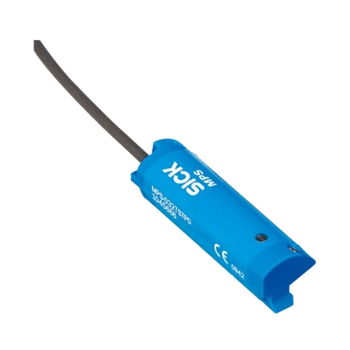
SICK 1050918 MPS-032TSNU0 Analog Cylinder Position Sensor

USD 310.44

MPS-032TSNU0 measures cylinder position over 32 mm, with either 0–10 V or 4–20 mA output, T-slot mounting, IP67 and a 2 m PUR cable.

SKU SICK-1050918 Category
SICK MPS-T

SICK MPS-032TSNU0 Analog Cylinder Position Sensor

BrandSICK
Model IdentifierMPS-032TSNU0
Official Part Number1050918

Technical Overview

The SICK MPS-032TSNU0 is a magnetic cylinder-position sensor for T-slot mounting, with a 32 mm measuring range and 45 mm housing. Its analog interface provides either 0–10 V or 4–20 mA, activating only the output that is wired. The sensor has no teach-in function. A 2 m stripped four-wire PUR cable carries power and the analog connections to an external controller. The 15–30 V DC device has a typical 0.3 mm linearity error at +25 °C, subject to the documented response conditions. A plastic IP67 housing, local status indicator and reverse-polarity and short-circuit protection support installation, with operation from −20 to +70 °C.

32 mm T-slot cylinder-position sensor with either 0–10 V or 4–20 mA output, no teach-in and 2 m stripped four-wire PUR cable.

Key Features

  • Magnetic cylinder-position measurement in a T-slot housing
  • 32 mm measuring range, specified ±1 mm; 45 mm housing length
  • Either 0–10 V or 4–20 mA analog output; only the wired output is activated
  • Typical 1 ms sampling interval in standard operation
  • Fixed measuring configuration without teach-in
  • 2 m stripped four-wire PUR cable; axial cable outlet
  • 15–30 V DC; 22 mA consumption without load
  • Typical required magnetic field 4–30 mT; typical linearity error 0.3 mm at +25 °C
  • Reverse-polarity and short-circuit protection; status LED
  • Plastic housing; IP67 according to EN 60529; −20 to +70 °C operation

Read cylinder position through the wired voltage or current output to give external control a continuous position reference.

Technical Specification Matrix

ParameterValue
Functional principleMagnetic cylinder-position measurement
Cylinder typeT-slot
Cylinder types with adapterRound body; profile and tie-rod; dovetail groove cylinders; suitable adapter required
Measuring range32 mm, specified ±1 mm
Housing length45 mm
Power supply15–30 V DC
Current consumption22 mA without load
Protection classIII
Availability delay1.5 s
Magnetic field requirementTypically 4–30 mT
Typical linearity error0.3 mm at +25 °C; maximum deviation depends on response curve and minimum-deviation function
Circuit protectionReverse-polarity and short-circuit protection
Status indicatorLED
Connection2 m stripped four-wire PUR cable
Electrical wiringDC four-wire
Cable outletAxial
Cable diameterØ2.6 mm
Conductor cross-section0.08 mm²
Bending radiusFixed installation >5× cable diameter; flexible use >10× cable diameter
Cable handlingDo not bend below 0 °C
Cable materialPUR
Housing materialPlastic
MountingSW1.5 fixing screws; 0.25–0.35 Nm tightening torque
Mounting screw spacing40 mm
IP ratingIP67 according to EN 60529
Operating temperature−20 to +70 °C
Shock resistance30 g, 11 ms
Vibration resistance10–55 Hz, 1 mm
EMCEN 60947-5-7
UL filesNRKH.E181493 and NRKH7.E181493
MTTFD387 years
DCavg0%
Mission time20 years
Output functionAnalog
Analog outputEither 0–10 V or 4–20 mA; only the wired output is activated
Current-output load≤500 Ω at 24 V supply
Voltage-output load≥2 kΩ
Teach-inNone
Typical sampling interval1 ms in standard operation
EMC transient conditionAnalog measured value can deviate for up to 100 ms under transient conditions
Conductor functionsCD-359: BN=L+; BK=Uout; WH=Iout; BU=M

Industrial Applications

1. Evaluating a cylinder stop position against a process window

A cylinder-driven positioning fixture can feed the sensor voltage or current signal into a matching external analog input. The controller compares the settled position with a commissioned process window within the 32 mm measuring range. Setup accounts for the actual cylinder magnet and the typical 0.3 mm linearity error, rather than treating the range tolerance as measurement accuracy.

Problem Solved

A measured position value lets external fixture logic evaluate a process window around the intended stop, helping distinguish acceptable travel from a displaced settled position.

Position window Analog input 32 mm range

2. Classifying gripped components from actuator position

A cylinder-operated gripper can use its measured actuator position as an indirect indication of the opening established around a component. External logic compares the settled analog value with commissioned part classes. The application establishes the relationship between actuator movement and jaw geometry, and uses class separations that accommodate actual mechanics, magnet behavior and the stated linearity performance.

Problem Solved

A continuous actuator-position signal gives external gripper logic a basis for distinguishing sufficiently separated opening classes, helping identify a differently sized or missing component after gripping.

Grip opening classes Settled position External comparison

3. Reviewing cylinder travel over time for a stalled move

A machine controller can record the selected analog output during a commanded cylinder movement and compare position progression with elapsed time. A sustained plateau before the expected travel endpoint becomes a process-monitoring condition in external logic. The typical 1 ms standard-mode sampling interval provides the sensor-side timing reference, while the analog input scan and transient behavior are included in the recording design.

Problem Solved

A position-versus-time record lets external process logic identify a sustained lack of expected movement, helping distinguish a stalled travel event from normal completion at the intended endpoint.

Travel monitoring Analog recording Stall condition

Select your currency