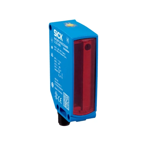
SICK 1221060 RAY26P-24162330A00 55 mm IO-Link Reflex Array Sensor

USD 297.44

55 mm Reflex Array with selectable 3/5/10 mm minimum object size, PL80A ranges to 2/3/4.5 m, conveyor-belt suppression, AutoAdapt and IO-Link V1.1.

SKU SICK-1221060 Category
SICK RAY26 Reflex Array

SICK RAY26P-24162330A00 55 mm IO-Link Reflex Array Sensor

BrandSICK
Model IdentifierRAY26P-24162330A00
Official Part Number1221060

Technical Overview

The SICK RAY26P-24162330A00 is a retro-reflective Reflex Array sensor covering a 55 mm detection height with visible 635 nm PinPoint light. Coaxial optics permit operation without a reflector minimum distance. With PL80A, the maximum range is 2 m for 3 mm minimum objects, 3 m for 5 mm and 4.5 m for 10 mm. BluePilot teaching, IO-Link adjustment and conveyor-belt suppression establish the detection arrangement, while AutoAdapt and quality diagnostics support setup and maintenance. Push-pull outputs and IO-Link V1.1 provide switching information to external control. The 10–30 V DC device has an M12 four-pin connector, VISTAL housing, PMMA optics and IP66/IP67 protection.

55 mm retro-reflective Reflex Array with configurable 3/5/10 mm minimum objects, conveyor-belt suppression, push-pull outputs and IO-Link V1.1.

Key Features

  • 55 mm Reflex Array detection height with coaxial retro-reflective optics
  • 3 mm factory minimum object size; 5 mm or 10 mm selectable via IO-Link
  • PL80A maximum range 2/3/4.5 m for 3/5/10 mm minimum objects respectively
  • 635 nm red PinPoint LED; 55 ×9 mm spot at 1 m
  • BluePilot teach-in, AutoAdapt and manual/IO-Link conveyor-belt suppression
  • Push-pull PNP/NPN outputs; configurable MF pin and QL1/C switching/IO-Link pin
  • IO-Link V1.1 COM2; 16-bit process data; 2.3 ms cycle
  • Base logics and timer functions; quality-of-teach/run and contamination diagnostics
  • ≤3 ms response and 170 Hz in switching mode under specified conditions
  • 10–30 V DC; M12 four-pin connector; VISTAL/PMMA; IP66/IP67

Detect objects at different heights within a 55 mm light array, with local or IO-Link belt suppression and IO-Link minimum-object selection.

Technical Specification Matrix

ParameterValue
Functional principleRetro-reflective Reflex Array; autocollimation/coaxial optics, no reflector minimum distance
Detection height55 mm
Minimum object size3 mm factory setting; 5 mm or 10 mm configurable via IO-Link, with adjustable conveyor-belt suppression; position-independent within the light array
PL80A ranges0–2 m at 3 mm minimum object size; 0–3 m at 5 mm; 0–4.5 m at 10 mm
Other reflector rangesPL81 and PL100: 0–2 m at 3 or 5 mm minimum object size; 0–3 m at 10 mm
Conveyor-belt suppressionManual or via IO-Link
Light source635 nm visible red PinPoint LED
Light spot size55 ×9 mm at 1 m
Average LED life100,000 h at +25 °C
AdjustmentBluePilot teach-in and IO-Link
AutoAdaptProvided
Manufacturer special applicationsObjects with position tolerances; perforated, uneven, shiny, transparent and flat objects
Digital outputsPush-pull PNP/NPN; QL1/C on pin 4, MF on pin 2; do not connect either switching output to another output
Switching modesLight/dark selection via IO-Link
Factory output mappingPin 2 MF: NPN NC/light switching or PNP NO/dark switching; pin 4 QL1/C: NPN NO/dark switching or PNP NC/light switching, with IO-Link
Pin 2 functionsExternal test input, teach-in or switching signal
PNP signal HIGH/LOWApproximately Vs −2.5 V / 0 V
NPN signal HIGH/LOWApproximately Vs / <2.5 V
Output current≤100 mA
Response time≤3 ms in switching mode with resistive load; COM2 mode may differ
Switching frequency170 Hz at 1:1 light/dark ratio in switching mode; IO-Link mode may differ
Smart Task timingSIO Direct / SIO Logic / IOL: 170 Hz, 3 ms response and 1.5 ms repeatability under the documented mode conditions
Logic functionsBase logics: Direct, AND, OR, window and hysteresis; inverter provided
Timer functionsDeactivated; switch-on delay; off delay; ON and OFF delay; impulse/one shot
DiagnosisDevice status; quality of teach; quality of run with contamination display
IO-LinkV1.1; COM2, 38.4 kBaud; 2.3 ms cycle
Process data16 bits: bit 0=QL1; bit 1=QL2; bits 2–15 empty
IO-Link identifiersVendorID 26; DeviceID hex 0x800217 / decimal 8389143
Master compatibilityPort type A; SIO mode supported
Power supply10–30 V DC
Ripple<5 Vpp
Current consumption25 mA at 16–30 V DC; 40 mA at 10–16 V DC; without load
ConnectionM12 four-pin male connector
Pin assignmentCD-390: 1 BN=L+; 2 WH=MF; 3 BU=M; 4 BK=QL1/C
Circuit protectionSupply and input/output reverse-polarity protection; interference suppression; output overcurrent and short-circuit protection
Protection classIII
Housing materialVISTAL plastic
Optics materialPMMA plastic
IP ratingIP66 / IP67
Operating temperature−40 to +60 °C; avoid front-screen and reflector condensation; allowed temperature change after teach ±20 K
Storage temperature−40 to +75 °C
IndicatorsBlue BluePilot AutoAdapt indication in run mode; yellow received-light indicator; green power indicator
MountingØ5.2 mm mounting holes
MTTFD709 years
DCavg0%
UL fileNRKH.E181493 and NRKH7.E181493
Physical Weight (kg)0.08

Industrial Applications

1. Counting flat products with varying presentation height

A conveyor can carry flat products whose leading edges do not consistently intersect one narrow optical spot. The 55 mm Reflex Array provides position-independent detection within its light array, while conveyor-belt suppression defines the intended belt boundary. External counting logic reads switching transitions after commissioning verifies product geometry, selected minimum object size, reflector type and spacing against the associated range and timing.

Problem Solved

A vertically extended detection condition helps external counting logic register flat products despite presentation-height variation, with belt suppression distinguishing the intended product region from the conveyor.

Flat-product counting 55 mm array Belt suppression

2. Detecting perforated carriers along a transfer path

A transfer path can present perforated carriers across the light array and use the sensor’s manufacturer-listed perforated-object capability as a process-presence input. The array covers a 55 mm vertical region rather than one isolated beam spot. Commissioning evaluates the actual opening pattern, carrier structure and selected minimum-object setting, then configures output behavior appropriate to external carrier sequencing.

Problem Solved

An array-based process condition helps external transfer logic evaluate perforated carriers across the selected detection region, reducing dependence on one fixed spot landing on solid material.

Perforated carrier Array detection Transfer sequencing

3. Planning cleaning from optical quality diagnostics

A maintenance system can read the documented quality-of-run and contamination diagnostics through the sensor integration while the line presents representative products and reflector conditions. Quality-of-teach information supports commissioning checks, and the BluePilot AutoAdapt indication provides a local operating reference. The maintenance procedure relates those observations to the actual optical surfaces and compares conditions before and after cleaning.

Problem Solved

Optical-quality information gives maintenance a condition reference beyond the final switching state, helping schedule inspection and assess cleaning work on the sensor and reflector.

Contamination diagnostics Quality of run Maintenance
Select your currency