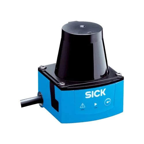
| Product type | Indoor 2D LiDAR sensor |
| Measurement principle | HDDM+ |
| Light source | 850 nm infrared laser |
| Laser class | Class 1; IEC 60825-1:2014 and EN 60825-1:2014+A11:2021 |
| Horizontal aperture angle | 270° |
| Horizontal angular resolution | 1° |
| Scanning frequency | 15 Hz |
| Working range | 0.05–4 m |
| Range at 10% remission | 2 m |
| Response time | One scan: typically 67 ms; two scans: ≤134 ms over +45° to +225°, maximum 150 ms over −45° to +45° |
| Detectable object shape | Almost any |
| Systematic error | ±40 mm, typical at 90% remission up to maximum scanning range; actual value depends on ambient conditions |
| Statistical error | <30 mm, typical at 90% remission up to maximum scanning range; actual value depends on ambient conditions |
| Integrated application | Field evaluation |
| Field sets | 16 field triples, 48 fields; one triple of three fields can be configured directly at scanner |
| Simultaneous evaluation | One evaluation case, three fields |
| Digital inputs | Four |
| Digital outputs | Three NPN field outputs plus one Device Ready output |
| Output current | ≤100 mA |
| Delay time | 67–30,000 ms, configurable |
| Dwell time | 67–600,052 ms, configurable |
| Service interface | Micro USB for service and parameterization; type B female connector |
| Local controls | Function button for teach-in; two red/green LEDs for ON and switching status |
| Connection | 0.9 m cable with 15-pin D-Sub HD male connector for power/digital I/O |
| D-Sub HD pin assignment | 1=9–28 V DC; 2/3/6/7=not connected; 4=OUT4; 5=GND; 8=IN1; 9=IN2; 10=IN3; 11=IN4; 12=OUT1; 13=OUT2; 14=OUT3; 15=IN GND for PNP inputs or IN 9–28 V for NPN inputs |
| Power supply | 9–28 V DC |
| Power consumption | Typically 4 W; 16 W with four digital outputs maximally loaded |
| Housing color | Light blue, RAL 5012 |
| IP rating | IP65, IEC 60529:1989+AMD1:1999+AMD2:2013 |
| Protection class | III, IEC 61140:2016-1 |
| Mounting | M3 blind threaded holes, 2.8 mm deep; maximum 0.8 Nm |
| Items supplied | Two straight mounting plates with M3 × 4 mm screws |
| Alignment features | Emission-plane position mark and 90° bearing mark; keep mounted reflective surfaces outside the indicated exclusion area |
| Remission range | 4–1,000%, including reflectors |
| Operating temperature | −10 to +50 °C |
| Switch-on temperature | −10 to +50 °C |
| Storage temperature | −30 to +70 °C |
| Relative humidity | Operation <80%; storage ≤90%; non-condensing, EN 60068-2-30:2005 |
| Ambient light immunity | 80,000 lx |
| Vibration resistance | Sine resonance scan 10–1,000 Hz; sine test 10–500 Hz, 5 g, 10 frequency cycles, IEC 60068-2-6:2007; noise 10–250 Hz, 4.24 g RMS, 5 h, IEC 60068-2-64:2008 |
| Shock resistance | 50 g, 11 ms, ±3 single shocks/axis; 25 g, 6 ms, ±1,000 continuous shocks/axis; 50 g, 3 ms, ±5,000 continuous shocks/axis; IEC 60068-2-27:2008 |
| Temperature-change test | −10 to +50 °C, 10 cycles; EN 60068-2-14:2009 |
| Damp-heat test | +25 to +55 °C, 95% RH, six cycles; EN 60068-2-30:2005 |
| EMC emission | Residential area; EN 61000-6-3:2007+AMD:A1:2011 |
| EMC immunity | Industrial environment; EN 61000-6-2:2005 |
| MTBF | >100 years |
| MTTFD | 100 years |
| Manufacturer use classification | Process field evaluation; sensor does not constitute a safety component under machine-safety legislation |