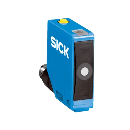
SICK 6077703 UC12-1223E IO-Link Ultrasonic Distance Sensor

USD 387.14

55–250 mm ultrasonic operation with 350 mm limiting range, IO-Link V1.1, complementary push-pull outputs, teach-in, 25 Hz switching and M12 connection.

SKU SICK-6077703 Category
Ultrasonic Distance Sensors - SICK UC12

SICK UC12-1223E IO-Link Ultrasonic Distance Sensor

BrandSICK
Model IdentifierUC12-1223E
Official Part Number6077703

Technical Overview

The SICK UC12-1223E is a straight-axis ultrasonic distance sensor with a 55–250 mm operating range and 350 mm limiting range. Its typical ultrasonic frequency is 500 kHz, with temperature compensation, 30 ms response and 8 ms output time. Two complementary push-pull outputs provide configured distance, window or object-between-sensor-and-background conditions; IO-Link V1.1 carries process data, parameters and diagnosis and supports data storage. Teach-in sets digital outputs, and the local teach button can be deactivated. Detection depends on the target’s reflection properties, size and alignment. The 10–30 V DC unit uses an M12 four-pin connector and zinc die-cast housing with IP65/IP67 protection.

55–250 mm ultrasonic distance sensor with 350 mm limiting range, IO-Link V1.1, complementary push-pull outputs, teach-in and M12 four-pin connection.

Key Features

  • 55–250 mm operating range; 350 mm limiting range
  • Typical ultrasonic frequency 500 kHz; straight sending axis
  • Temperature compensation; resolution ≥0.1 mm
  • Repeatability ±0.15% of measured value, with resolution floor
  • Measurement accuracy ±1% of current measured value
  • 30 ms response, 25 Hz switching and 8 ms output time
  • Two complementary push-pull PNP/NPN outputs; ≤100 mA; 2 mm hysteresis
  • Distance, window and object-between-sensor-and-background switching modes
  • IO-Link V1.1: process data, parameters, diagnosis and data storage
  • 10–30 V DC, M12 four-pin connector; zinc die-cast housing and IP65/IP67

Teach ultrasonic switching conditions and communicate them through complementary outputs or IO-Link, using a detection area matched to the actual target geometry.

Technical Specification Matrix

ParameterValue
Functional principleUltrasonic distance sensing
Operating range55–250 mm
Limiting range350 mm
Resolution≥0.1 mm
Repeatability±0.15% of current measured value; minimum value ≥resolution
Measurement accuracy±1% of current measured value
Temperature compensationProvided
Response time30 ms
Switching frequency25 Hz
Output time8 ms
Ultrasonic frequencyTypical 500 kHz
Detection geometryDepends on reflection properties, size and alignment; manufacturer diagrams use aligned 10 ×10 mm plate and Ø10 mm cylindrical bar examples
Switching modesDistance to object (DtO); window (Wnd); object between sensor and background (ObSB)
Output adjustmentDigital-output teach-in; teach buttons can be deactivated; reset to factory defaults
Communication interfaceIO-Link V1.1
IO-Link functionsProcess data, parameterization, diagnosis and data storage
Digital outputsTwo complementary push-pull PNP/NPN outputs, Q and Q̅
Maximum output current≤100 mA
Output HIGH/LOWHIGH: supply minus voltage drop <0.6 V; LOW: <0.6 V
Hysteresis2 mm
Power supply10–30 V DC; reverse-polarity protected; short-circuit-protected network, maximum 8 A
Power consumption≤1.2 W without load
Initialization time<300 ms
IndicatorsOne LED; output status orange and power on green
Housing designRectangular; straight sending axis
Housing materialZinc die-cast metal; ultrasonic transducer: polyurethane foam and glass epoxy resin
ConnectionM12 four-pin male connector
Pin assignment1 BN=L+; 3 BU=M; 4 BK=Q/Q̅/IO-Link C; 2 WH=Q̅/Q
MountingM4 threaded mounting holes, 4 mm deep; fixing hole shown Ø4.2 mm
IP ratingIP65/IP67
Protection classIII
Operating temperature−25 to +70 °C
Storage temperature−40 to +85 °C
Physical Weight (kg)0.075

Industrial Applications

1. Checking a fixture surface against a distance window

An inspection fixture can hold a component so that its echo-producing face lies within the 55–250 mm operating range. A taught window reports whether the surface falls between configured distance limits, and external inspection logic reads the complementary outputs. Target size, alignment and reflection properties define the usable echo geometry, while the acceptance band accounts for the stated accuracy and repeatability.

Problem Solved

A taught ultrasonic window gives external inspection logic a surface-position condition, helping distinguish an expected fixture presentation from a part that lies outside the configured band.

Fixture window Ultrasonic echo Complementary outputs

2. Detecting an item entering a taught background path

A handling station can teach the documented object-between-sensor-and-background mode with a stable echo-producing background. An item crossing that acoustic path changes the taught condition, and external sequencing uses the resulting output event. Setup places the relevant surfaces within the verified detection geometry and accounts for the 30 ms response, 25 Hz switching and 2 mm hysteresis.

Problem Solved

A background-referenced ultrasonic condition gives external sequencing an intervening-item event, helping recognize entry into the taught acoustic path during the handling operation.

Background reference ObSB mode 25 Hz

3. Applying ultrasonic sensor settings with a machine recipe

A machine that presents different component geometries can keep sensor settings in its external recipe system and apply them through IO-Link parameterization. IO-Link also supplies process data and diagnosis and supports data storage, while the teach button can be deactivated after setup. The recipe uses verified target geometry and working distances to define the intended ultrasonic switching conditions.

Problem Solved

Digital parameter access gives external recipe control a sensor-configuration path, helping apply the intended ultrasonic setup and review diagnostic information when the presented component changes.

Recipe settings IO-Link V1.1 Data storage

Select your currency