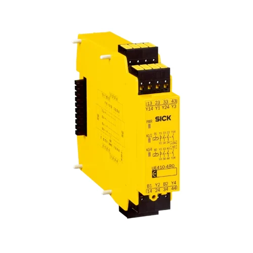
SICK 6032676 UE410-4RO4 Four-path Relay Output Module

USD 451.36

UE410-4RO4 provides four positively guided enabling contacts, two wired control inputs, two feedback circuits and plug-in spring terminals.

SKU SICK-6032676 Category
SICK Safety Controllers

SICK UE410-4RO4 Four-path Relay Output Module

BrandSICK
Model IdentifierUE410-4RO4
Official Part Number6032676

Technical Overview

The SICK UE410-4RO4 is a hard-wired relay output module with four potential-free, positively guided normally-open enabling contacts. Two control inputs, B1 and B2, each operate a redundant two-contact group, with a separate feedback circuit and internally supplied signaling output for each group. FLEXBUS+ supplies the module, while control commands use wired inputs. In the documented Flexi Soft arrangement, FX3-XTIO outputs drive B1/B2 and an EDM function block monitors the feedback contacts; the relay module does not receive control through internal bus communication. Plug-in spring terminals and relay-state LEDs support cabinet installation. The exact datasheet lists SIL 3, Category 4 and PL e module ratings, with IP40 housing and IP20 terminal protection.

Relay output module with four positively guided enabling contacts, B1/B2 control, two feedback circuits, FLEXBUS+ supply and plug-in spring terminals.

Key Features

  • Four potential-free positively guided normally-open enabling contacts
  • B1 controls 13/14 and 23/24; B2 controls 33/34 and 43/44
  • Two potential-free normally-closed feedback circuits: Y1/Y2 and Y3/Y4
  • Two current-limited internally supplied signaling outputs: Y14 and Y24
  • FLEXBUS+ supply; wired B1/B2 inputs at 18–30 V DC
  • Flexi Soft integration uses FX3-XTIO control outputs and EDM feedback monitoring
  • Maximum 30 ms from LOW at B1/B2 to relay drop-out in the documented manual
  • Module ratings listed: SIL 3, Category 4, PL e
  • Plug-in spring terminals; power and two relay-group LEDs
  • ≤3.2 W consumption; IP40 housing, IP20 terminals; −25 to +55 °C operation

Add two independently controlled redundant contact groups to a compatible safety-control arrangement, with positively guided feedback contacts for EDM monitoring.

Technical Specification Matrix

ParameterValue
Product typeHard-wired relay output module
Enabling contactsFour potential-free NO contacts, positively guided: 13/14, 23/24, 33/34, 43/44
Control groupsB1: 13/14 and 23/24; B2: 33/34 and 43/44; independently redundant switch-off groups
Control inputsTwo, B1/B2; ON voltage 18–30 V DC
Enabling-contact switching voltage5–253 V AC/DC; apply load-dependent usage ratings
Enabling-contact switching current10 mA–6 A; module total-current limit 8 A per hardware manual
Feedback circuitsY1/Y2 and Y3/Y4; potential-free NC contacts, positively guided
Feedback contact ratings5–253 V AC/DC; 10 mA–6 A
Signaling outputsY14/Y24; NO contacts connected to internal 24 V DC, positively guided and current-limited
Signaling output voltage16–30 V DC
Signaling output current≤75 mA
SupplyVia FLEXBUS+
Power consumption≤3.2 W; internal consumption via FLEXBUS+ ≤3.2 W
Bus behaviorNo internal FLEXBUS+ control communication; commands use wired B1/B2 inputs
Documented Flexi Soft integrationFX3-XTIO Q outputs wired to B1/B2; feedback circuits must be monitored by an EDM function block
Flexi Soft expansion limitUp to four UE410-4RO modules, providing up to 16 relay enabling outputs
Relay drop-out response≤30 ms from LOW at B1/B2 to relay drop-out; hardware manual
Contact materialAgSnO2; hardware manual
Mechanical enduranceMinimum 10 million operations; hardware manual
Minimum contact load50 mW at 24 V DC; hardware manual
Output fusing6 A gG per current path; hardware manual
Utilization ratingsAC-15: 250 V, 3 A; DC-13: 24 V, 3 A; hardware manual
ConnectionPlug-in spring terminals
IndicationGreen PWR: supply present; green K1/2 and K3/4: respective safety contacts closed
SIL ratingSIL 3; IEC 61508
Category ratingCategory 4; EN ISO 13849
Performance levelPL e; EN ISO 13849
Protection classIII; EN 61140
Overvoltage categoryII; EN 61131-2
IP ratingHousing IP40; terminals IP20; EN 60529
Operating temperature−25 to +55 °C
Storage temperature−25 to +70 °C
Relative humidity≤95%; non-condensing
Climatic conditionsEN 61131-2: +55 °C ambient and 95% relative humidity
EMCClass A; EN 61000-6-2 and EN 55011

Industrial Applications

1. Providing relay isolation for externally controlled contactor circuits

A machine cabinet can use one redundant relay group between a compatible safety controller’s decision and external contactor-control circuits. In the documented Flexi Soft arrangement, FX3-XTIO outputs drive the wired control input and the controller monitors the corresponding feedback circuit through EDM. Contact selection observes the actual load category, module total-current limit, per-path fusing and relay drop-out contribution to the function’s timing.

Problem Solved

Potential-free positively guided contacts provide an isolated switching interface for external contactor-control circuits, helping translate the controller’s wired command into monitored relay contact operation.

Contactor interface Potential-free contacts EDM feedback

2. Separately switching two machine enable branches

A machine with two separately commanded enable branches can assign B1 to the first two-contact group and B2 to the second. The compatible controller issues each wired command according to its configured sequence and monitors each group’s own feedback circuit. The two groups provide independently redundant switch-off paths; cabinet design applies the shared current limit and the appropriate contact ratings to both branches.

Problem Solved

Two controlled relay groups let a compatible controller operate separate enable branches with individual feedback references, helping coordinate distinct machine sections through monitored contact paths.

Two enable branches B1/B2 Separate feedback

3. Monitoring relay-group return during a restart sequence

A controller-managed restart sequence can evaluate Y1/Y2 and Y3/Y4 after commanding the relay groups off. The positively guided NC feedback circuits are monitored through the required EDM function block in the documented Flexi Soft arrangement. External logic compares feedback with its expected sequence before issuing its next enable command, while the group LEDs support local cabinet diagnosis.

Problem Solved

Positively guided feedback contacts give the controller an observed relay-state reference, helping its EDM logic identify a relay group that has not returned as expected.

Relay return EDM sequence Group indication

Select your currency