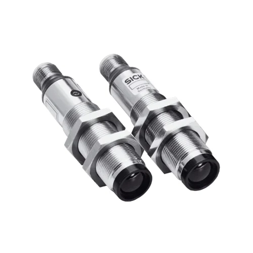
SICK 6013675 VS/VE18-4P3112 PNP Through-beam Sensor Pair

USD 131.04

VS/VE18-4P3112 offers 0–14 m infrared through-beam sensing, PNP output, control-wire light/dark selection, sender Test and metal M18 housing.

SKU SICK-6013675 Category
SICK V18

SICK VS/VE18-4P3112 PNP Through-beam Sensor Pair

BrandSICK
Model IdentifierVS/VE18-4P3112
Official Part Number6013675

Technical Overview

The SICK VS/VE18-4P3112 is an infrared through-beam photoelectric sensor pair with axial optics in nickel-plated brass M18 × 1 housings. It provides a 0–14 m sensing range and 0–20 m maximum range, with a 700 mm spot at 14 m and approximately 2.8° dispersion. There is no sensitivity adjustment. The receiver’s single PNP output supports light/dark selection through its L/D wire, defaulting to dark switching when that wire is open. Response is no more than 2 ms with resistive load, with 250 Hz switching. The sender Test input turns illumination off at 0 V. Receiver wiring uses a 2 m four-wire PVC cable, and the pair provides IP67 protection with operation from −25 to +70 °C.

Metal M18 infrared through-beam pair with 0–14 m sensing, PNP output, control-wire light/dark selection and sender Test input.

Key Features

  • Separate sender and receiver for infrared through-beam sensing
  • 0–14 m sensing; 0–20 m maximum range
  • Ø700 mm spot at 14 m; approximately 2.8° dispersion
  • Single PNP output; light/dark selection through receiver L/D wire
  • Open L/D wire defaults to dark switching
  • Response ≤2 ms with resistive load; 250 Hz at 1:1 light/dark ratio
  • Sender Test input switches illumination off at 0 V
  • Receiver: 2 m four-wire PVC cable, 0.14 mm² conductors
  • Nickel-plated brass M18 × 1 housings with axial optics; IP67
  • 10–30 V DC; −25 to +70 °C operation; no sensitivity adjustment

Monitor an infrared beam path over 0–14 m and use sender Test to provide a controlled optical interruption for an ordinary response check.

Technical Specification Matrix

ParameterValue
Functional principleInfrared through-beam photoelectric sensor pair
Sensing range0–14 m
Maximum sensing range0–20 m
Light sourceInfrared LED
Average LED service life100,000 h at +25 °C
Light spot sizeØ700 mm at 14 m
Focus and dispersion angleApproximately 2.8°
Sensitivity adjustmentNone
Switching outputSingle PNP
Switching modeLight/dark selectable through receiver L/D control wire; open wire gives dark switching (D.ON)
Output current≤100 mA
Response time≤2 ms signal transit time with resistive load
Switching frequency250 Hz at 1:1 light/dark ratio
Test inputSender OFF with TE at 0 V
Receiver connection2 m four-wire PVC cable; 0.14 mm² conductors; diameter 5 mm; do not bend below 0 °C
Sender conductor functionsCD-221: BN=L+; BU=M; BK=Test
Receiver conductor functionsCD-221: BN=L+; BU=M; BK=Q; WH=L/D
Power supply10–30 V DC
Ripple±10%; remain within supply-voltage tolerances
Current consumption30 mA without load
Circuit protectionSupply and input/output reverse-polarity protection; interference suppression; output overcurrent and short-circuit protection
Protection classIII
Housing designCylindrical, axial optics
Mounting threadM18 × 1
Housing materialNickel-plated brass
Nominal housing length63.6 mm
IP ratingIP67
IndicationSender: yellow operating indicator; receiver: yellow received-light indicator
Operating temperature−25 to +70 °C
UL fileNMFT2.E175606

Industrial Applications

1. Counting separated opaque loads through a conveyor lane

A conveyor can mount the sender and receiver on opposite sides of separated opaque loads. Each interruption of the infrared path provides a PNP event to external counting electronics. Setup aligns the opposed optics over the installed separation and assesses load spacing and passage time against the 0–14 m sensing range, 250 Hz rating and resistive-load response.

Problem Solved

Direct-beam interruptions provide discrete passage events to external counting electronics, helping track separated loads across the conveyor lane with opposed infrared optics and selectable output logic.

Load counting Infrared path 250 Hz

2. Monitoring material continuity at a fixed web threshold

A web-handling station can position the direct beam across a location normally covered by opaque material. An open gap clears the beam and changes the receiver’s selected PNP condition, which external monitoring times against the expected process sequence. The L/D control wire sets output behavior, and the installed optical separation remains within the documented range.

Problem Solved

A sustained clear-path condition supplies external web monitoring with a continuity reference, helping identify an open material gap at the selected threshold during normal production.

Web continuity L/D control External timing

3. Checking the optical response through the sender Test input

A service routine can connect the sender’s Test input to 0 V while the receiver normally sees the unobstructed beam. The deliberate sender-off stimulus changes the received-light condition and lets external diagnostics compare the PNP input response with the configured light/dark logic. The routine coordinates this ordinary response check with machine state and the documented response specification.

Problem Solved

A controlled sender-off stimulus gives external diagnostics a repeatable optical change, helping check the sensor input response during a scheduled service routine without moving a target.

Sender Test Input-response check Optical stimulus

Select your currency