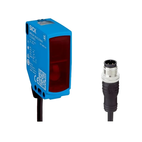
| Functional principle | Polarized photoelectric retro-reflective sensing |
| Optical arrangement | Autocollimation/coaxial optics; no minimum reflector distance |
| Maximum reflector distance | 0–10 m with PL80A, operating reserve 1 |
| Recommended reflector distance | 0–7 m with PL80A, operating reserve 3.75 |
| Reference reflector | PL80A |
| Polarization filter | Provided |
| Light spot size | Ø80 mm at 5 m |
| Manufacturer special application | Detecting objects wrapped in film |
| Adjustment | IO-Link configures sensor parameters and Smart Task functions |
| BluePilot alignment aid | Blue LEDs indicate alignment; all blue LEDs illuminated indicates optimal alignment and maximum possible operating reserve |
| Indicators | Green steady: power; green flashing: IO-Link; yellow steady: object absent; yellow off: object present; yellow flashing: function reserve below 1.5 |
| Default pin 4 function | BK: dark-switching output, object present → HIGH; IO-Link communication C |
| Default pin 2 function | WH: light-switching output, object present → LOW |
| Pin assignment | CD-390: 1 BN=L+; 3 BU=M; 4 BK=output / IO-Link C; 2 WH=multifunction output |
| Response time | ≤500 µs, signal transit with resistive load in switching mode |
| Response-time repeatability | 150 µs |
| Switching frequency | 1,000 Hz at 1:1 light/dark ratio |
| Smart Task switching frequency | SIO Logic: 800 Hz; IO-Link: 650 Hz |
| Smart Task response time | SIO Logic: 600 µs; IO-Link: 750 µs |
| Smart Task repeatability | SIO Logic: 300 µs; IO-Link: 750 µs |
| Diagnosis | Device status; quality of teach; quality of run with contamination display |
| Light source | Visible red PinPoint LED; 635 nm; point-shaped spot |
| Squint angle | <±1.0° at ambient +23 °C |
| LED photobiological classification | Free group; EN 62471:2008-09 / IEC 62471:2006, modified |
| Average LED service life | 100,000 h at ambient +25 °C |
| Communication interface | IO-Link V1.1; COM2, 38.4 kBaud |
| IO-Link cycle time | 2.3 ms |
| Process data | 16 bit: bit 0=QL1; bit 1=QL2; bits 2–15 empty |
| IO-Link identification | Vendor ID 26; Device ID 0x80016C / 8388972 |
| Compatible master port | Type A; SIO mode supported |
| Power supply | 10–30 V DC, limit values |
| Ripple | ≤5 Vpp |
| Usage categories | DC-12 and DC-13 to EN 60947-5-2 |
| Current consumption | ≤30 mA without load at 24 V DC |
| Protection class | III |
| Switching outputs | Two complementary push-pull PNP/NPN outputs |
| Switching mode | Light/dark switching; pin functions configurable via IO-Link |
| PNP signal voltage HIGH/LOW | Approximately supply voltage −2.5 V / 0 V |
| NPN signal voltage HIGH/LOW | Approximately supply voltage / <2.5 V |
| Output current | ≤100 mA |
| Output circuit protection | Reverse-polarity, overcurrent and short-circuit protection |
| Output connection restriction | A switching output must not be connected to another output |
| Connection | Cable with M12 four-pin male connector; overall connection assembly 318 mm |
| Housing design | Rectangular |
| Housing and male connector material | VISTAL plastic |
| Front screen material | PMMA plastic |
| Mounting holes | Ø4.1 mm |
| Maximum fixing-screw torque | 1.3 Nm |
| IP rating | IP66/IP67/IP69 to EN 60529 |
| IP69 designation note | Manufacturer states IP69 replaces IP69K to ISO 20653:2013-03 |
| Operating temperature | −40 to +60 °C |
| Storage temperature | −40 to +75 °C |
| Relative humidity | 35–95%, non-condensing |
| Shock resistance, 11 ms | 50 g; 25 positive and 25 negative shocks per X/Y/Z axis, 150 total; EN 60068-2-27 |
| Shock resistance, 6 ms | 50 g; 5,000 positive and 5,000 negative shocks per X/Y/Z axis, 30,000 total; EN 60068-2-27 |
| Vibration resistance | 10–2,000 Hz; 0.5 mm amplitude / 10 g; 20 sweeps per X/Y/Z axis at 1 octave/min; EN 60068-2-6 |
| EMC | EN 60947-5-2 |
| Cleaning-agent resistance | ECOLAB |
| UL files | NRKH.E181493 and NRKH7.E181493 |
| MTTFD | 690 years |
| DCavg | 0% |
| Mission time | 20 years |
| Smart Task | Base logics |
| Smart Task logic functions | Direct, AND, OR, window and hysteresis |
| Smart Task timer functions | Deactivated, switch-on delay, off delay, ON and OFF delay, impulse (one shot) |
| Smart Task inverter | Available |
| Reflector-range notation | Each triplet is minimum / recommended upper distance at operating reserve 3.75 / maximum upper distance at operating reserve 1, in metres |
| Reflective-tape ranges | 50 × 50 mm tape: REF-DG: 0 / 1 / 2; REF-IRF-56: 0 / 1.8 / 3; REF-AC1000: 0 / 4.5 / 6 |
| Standard-reflector ranges | PL22: 0 / 3.5 / 5; P250 and PL30A: 0 / 6 / 8; PL20A: 0 / 3 / 4; PL40A: 0 / 6.5 / 9; PL80A and C110A: 0 / 7 / 10 |
| Fine-triple reflector ranges | PL10FH-1: 0 / 3 / 4; PL10F: 0 / 2.5 / 3; PL20F: 0 / 3.8 / 5; P250F: 0 / 6 / 8 |
| Chemical-resistant and heated reflector ranges | PL10FCHEM: 0 / 1.4 / 2; PL20CHEM: 0 / 2.4 / 3.5; P250CHEM: 0 / 3.5 / 5; P250H: 0 / 4 / 6; PL40A Antifog: 0 / 6 / 8 |
| Cable length | 270 mm |
| Male connector length | 48 mm |
| Cable material | PVC |
| Conductor cross-section | 0.14 mm² |
| Cable diameter | 4.8 mm |
| Cable bending conditions | Flexible bending radius >12 × cable diameter; 1,000,000 bending cycles; do not bend below 0 °C |
| Physical Weight (kg) | 0.07 |