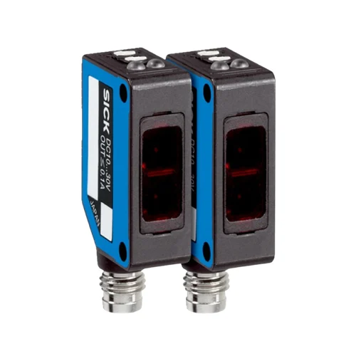
SICK 6030718 WS/WE100L-E2131 NPN Laser Through-beam Sensor

USD 259.22

WS/WE100L-E2131 offers 0–30 m laser through-beam sensing, NPN output, 2,000 Hz operation, a 270° sensitivity potentiometer and M8 three-pin connectors.

SKU SICK-6030718 Category
SICK W100 Laser

SICK WS/WE100L-E2131 NPN Laser Through-beam Sensor

BrandSICK
Model IdentifierWS/WE100L-E2131
Official Part Number6030718

Technical Overview

The SICK WS/WE100L-E2131 is a through-beam photoelectric sensor with separate sender and receiver units and a 650 nm visible red Class 1 laser. It specifies a 0–30 m sensing range and a 0–35 m maximum range, with a 30 mm light spot at 30 m. A 270° potentiometer adjusts sensitivity, and an L/D rotary switch selects light or dark switching for the receiver’s NPN output. Response is below 0.25 ms with a resistive load, and switching frequency is 2,000 Hz at a 1:1 light/dark ratio. Both units operate from 10–30 V DC with M8 three-pin connectors; ABS/PC/POM housings, PMMA optics, M3 mounting holes and two supplied stainless steel brackets support IP65 installations.

Class 1 red-laser through-beam sensor with 0–30 m range, NPN output, 2,000 Hz switching, local sensitivity and L/D controls, and M8 three-pin connectors.

Key Features

  • Separate sender and receiver for through-beam detection
  • 0–30 m sensing range; 0–35 m maximum range
  • 650 nm visible red laser; Class 1
  • Ø30 mm light spot at 30 m
  • 270° sensitivity potentiometer; L/D rotary switching selector
  • NPN output; ≤100 mA
  • Response <0.25 ms with resistive load; 2,000 Hz at 1:1 light/dark ratio
  • M8 three-pin connectors
  • M3 threaded mounting; two BEF-W100-A stainless steel brackets supplied
  • IP65 ABS/PC/POM housings and PMMA optics; −10 to +50 °C operation

Monitor interruptions of a directly transmitted laser beam with local sensitivity adjustment and selectable light/dark switching for the external controller.

Technical Specification Matrix

ParameterValue
Functional principleThrough-beam photoelectric sensing with separate sender and receiver
Housing designRectangular
Sensing range0–30 m
Maximum sensing range0–35 m
Light source650 nm visible red laser
Laser class1
Light-source service lifeAverage 50,000 h at +25 °C
Light spot sizeØ10 mm at 10 m; Ø20 mm at 20 m; Ø30 mm at 30 m
Adjustment270° sensitivity potentiometer
Switching outputNPN
Switching modeLight/dark switching, selected with L/D rotary switch
Signal voltage HIGH/LOWApproximately supply voltage / <1.8 V
Output current≤100 mA
Response time<0.25 ms with resistive load
Switching frequency2,000 Hz at light/dark ratio 1:1
Power supply10–30 V DC; limit values in a short-circuit-protected network, maximum 8 A
Ripple±10%; remain within supply-voltage tolerances
Sender current consumption≤15 mA without load
Receiver current consumption≤20 mA without load
ConnectionM8 three-pin connectors
Pin assignmentReceiver: 1 BN=L+; 3 BU=M; 4 BK=Q. Sender: 1 BN=L+; 3 BU=M; 4 not connected (CD-051)
Circuit protectionA: supply connections reverse-polarity protected; B: inputs and output reverse-polarity protected; D: outputs protected against overcurrent and short circuits
Housing materialABS/PC/POM plastic
Optics materialPMMA plastic
IP ratingIP65
MountingM3 threaded mounting holes; 25.4 mm spacing
Items suppliedTwo BEF-W100-A stainless steel mounting brackets, grade 1.4301/304
Operating temperature−10 to +50 °C
Storage temperature−40 to +70 °C
IndicatorsOrange: switching output active; green: power on
Manufacturer special applicationsDetecting small objects and objects moving at high speeds
MTTFD994 years
DCavg0%

Industrial Applications

1. Counting opaque components across a conveyor opening

A conveyor can carry separated opaque components between the sender and receiver. Each component interrupts the directly transmitted laser beam, and the receiver’s NPN output supplies transitions to external counting logic. The 270° potentiometer establishes working sensitivity, while setup verifies actual component coverage, alignment and transit timing against the spot size, response time and 2,000 Hz switching specification.

Problem Solved

Beam-interruption transitions help an external counter register separated components across an opening, with a dedicated receiver evaluating light sent directly from the opposite side.

Component counting Direct beam 2,000 Hz

2. Monitoring continuity of an opaque material web

A material guide can hold an opaque web across the beam path between the sender and receiver. Continuous material blocks the transmitted beam, while a missing section allows light to reach the receiver. The rotary L/D selector sets the output convention for external web-loss logic. Setup checks the actual web opacity, beam coverage, alignment and sensitivity at the guide.

Problem Solved

An interruption-state reference helps external process logic detect missing continuous material at the guide, using direct transmission rather than light reflected by the web surface.

Web continuity Beam restoration L/D selector

3. Flagging prolonged occupancy at a transfer opening

A transfer opening can place the sender and receiver on opposite sides of a carton path. A carton blocks the beam as it enters, giving an external dwell timer a discrete occupancy condition. External logic compares the blocked interval with the expected transfer time and flags prolonged obstruction. Installation checks alignment, actual carton coverage and the selected light/dark switching convention.

Problem Solved

A blocked-beam reference lets external timing logic identify a carton remaining at the opening beyond its transfer interval, helping locate a stalled movement.

Transfer dwell External timer Beam obstruction

Select your currency