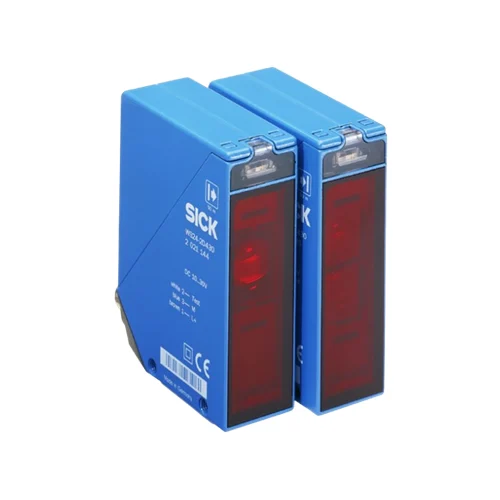
SICK 1017875 WS/WE24-2B440 Heated Through-Beam Sensor Pair

USD 483.60

50 m through-beam sensing, selectable PNP/NPN and light/dark operation, 0.5–10 s delays, M12 four-pin connections and low-output front-screen heating.

SKU SICK-1017875 Category
SICK W24

SICK WS/WE24-2B440 Heated Through-Beam Sensor Pair

BrandSICK
Model IdentifierWS/WE24-2B440
Official Part Number1017875

Technical Overview

The SICK WS/WE24-2B440 is a through-beam photoelectric sensor pair with separate red-LED sender and receiver, a 0–50 m sensing range and a 0–60 m maximum range. The receiver offers PNP/NPN and light/dark selectors, with switch-on and off delays adjustable from 0.5–10 s. A potentiometer, alignment sight and signal-strength LED support setup across the beam path. Permanent low-output front-screen heating is documented for +5 to +15 °C, separate from the sensor’s wider operating-temperature range. The 10–30 V DC units use M12 four-pin connections, zinc die-cast housings and PMMA front screens, with IP69K protection and a sender test input.

Red-LED through-beam pair with 50 m sensing range, selectable PNP/NPN and light/dark output, adjustable delays and low-output front-screen heating.

Key Features

  • Through-beam pair: sender WS24-2D440 and receiver WE24-2B440
  • 0–50 m sensing range; 0–60 m maximum range
  • Visible red LED; Ø700 mm spot at 50 m
  • Selectable PNP/NPN output and light/dark switching
  • Response ≤500 µs; 1,000 Hz at 1:1 light/dark ratio
  • Switch-on and off delays adjustable from 0.5–10 s
  • Permanent low-output front-screen heating for +5 to +15 °C use
  • M12 four-pin male connections; sender-off test input to 0 V
  • 10–30 V DC; 50 mA each sender and receiver without load
  • Zinc die-cast housings, PMMA front screens and IP69K

Use a separate sender and receiver to detect beam interruption, with selectable output logic and local delay functions for external machine sequencing.

Technical Specification Matrix

ParameterValue
Functional principleThrough-beam photoelectric sensing; separate sender and receiver
Individual componentsReceiver WE24-2B440, part 2021418; sender WS24-2D440, part 2021465
Sensing range0–50 m
Maximum sensing range0–60 m
Light sourceVisible red LED
Average LED service life100,000 h at +25 °C
Light spot sizeØ700 mm at 50 m
Focus and dispersionApproximately 1°
Angle of receptionApproximately 2.5°
AdjustmentSensitivity potentiometer; alignment sight; LED signal-strength indicator
Output selectionNPN/PNP changeover switch; light/dark selector
Switching outputSelectable PNP or NPN; selected Q or Q̅ function
Output current≤100 mA
Response time≤500 µs with resistive load
Switching frequency1,000 Hz at 1:1 light/dark ratio
Time functionsSwitch-on delay and off delay
Delay time0.5–10 s, adjustable via time controls and selector
Front-screen heatingPermanent, static low heat output; use in +5 to +15 °C; with plastic front screen
Test inputSender off when TE is connected to 0 V
ConnectionM12 four-pin male connector
Sender pin assignmentCD-118: 1 BN=L+; 2 WH=Test; 3 BU=M; 4=not connected
Receiver pin assignmentCD-118: 1 BN=L+; 2 WH=not connected; 3 BU=M; 4 BK=Q/Q̅
Power supply10–30 V DC; short-circuit-protected network, maximum 8 A
Ripple<5 Vpp; remain within supply-voltage tolerances
Sender current consumption50 mA without load
Receiver current consumption50 mA without load
Circuit protectionSupply reverse-polarity protection; interference suppression; output overcurrent and short-circuit protection
Protection classII; reference voltage 50 V DC
Housing designRectangular
Housing materialZinc die-cast metal
Optics materialPMMA plastic
IP ratingIP69K
MountingM5 threaded mounting holes: one 6 mm deep and one through-hole
Connection orientationM16 screw fixing and plug rotatable by 90°, as shown in manufacturer drawing
Operating temperature−40 to +60 °C
Storage temperature−40 to +75 °C
UL filesNRKH.E181493 and NRKH7.E181493
MTTFD392 years
DCavg0%
Mission time20 years

Industrial Applications

1. Counting separated loads across a conveyor opening

A conveyor can place the sender and receiver on opposite sides of an opening and send beam-interruption transitions to an external counter. The documented 0–50 m sensing range supports separation across the installation, while visible red light, the alignment sight and signal-strength indication assist setup. Load coverage and spacing govern usable events within the stated response and switching conditions.

Problem Solved

Direct beam interruption gives an external counter discrete load-passage events, helping track separated material without relying on light returned from each target surface.

Through-beam counting 50 m External counter

2. Qualifying prolonged occupancy at a transfer point

A transfer station can use continued beam interruption to identify an opaque load that remains in the handover position. The receiver’s local switch-on or off delay, selected to suit its light/dark output state, provides a qualified switching event to external sequencing. The 0.5–10 s adjustment distinguishes a brief passage from occupancy extending beyond the configured interval.

Problem Solved

Local timing gives external sequencing a duration-qualified occupancy event, helping distinguish normal movement from a load that remains across the transfer beam.

Transfer dwell 0.5–10 s delay Selectable logic

3. Testing the optical signal path during a machine check

A machine check can hold the physical beam path clear and connect the sender test input to 0 V to turn emission off. External diagnostic logic observes the receiver transition through its selected PNP/NPN and light/dark output configuration, accounting for any enabled local delays. Restoring emission provides a second controlled state for comparison with the expected response.

Problem Solved

Controlled sender-off operation gives external diagnostic logic a reproducible interruption, helping test the optical signal chain without moving a physical test target across the opening.

Sender test TE to 0 V Signal-chain check

Select your currency