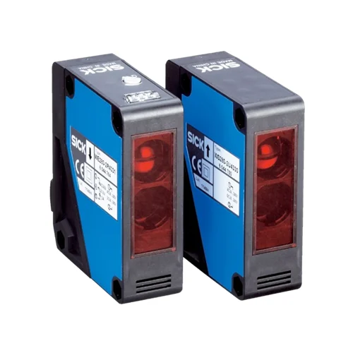
SICK 6044762 WSE280-2R4331 AC/DC Relay Through-beam Pair

USD 182.26

0–50 m sensing pair with isolated change-over contacts, 24–240 V AC/DC supply, 33 Hz switching, cable-gland connections and IP66/IP67 ABS housings.

SKU SICK-6044762 Category
SICK W280-2

SICK WSE280-2R4331 AC/DC Relay Through-beam Sensor Pair

BrandSICK
Model IdentifierWSE280-2R4331
Official Part Number6044762

Technical Overview

The SICK WSE280-2R4331 is a visible-red through-beam photoelectric sensor arrangement with separate sender and receiver. It provides a 0–50 m sensing range and 0–60 m maximum range, with a 0.6 m light spot at 20 m. The receiver uses a sensitivity potentiometer and an electrically isolated change-over relay output in light-switching operation. Contact ratings are 3 A at 240 V AC or 30 V DC, with response no greater than 15 ms and 33 Hz switching. Both units accept 24–240 V AC or DC supplies with ±10% tolerance and cable-gland connections. ABS housings with PMMA optics provide IP66/IP67 protection, and a BEF-W280 mounting bracket is listed.

Visible-red through-beam arrangement with 0–50 m sensing, isolated change-over relay output, 24–240 V AC/DC supply and IP66/IP67 protection.

Key Features

  • Separate optical sender and receiver; visible red LED
  • 0–50 m sensing range; 0–60 m maximum range
  • Ø0.6 m light spot at 20 m
  • Receiver sensitivity potentiometer and local received-light indication
  • Electrically isolated change-over relay contacts; light switching
  • Contact rating 3 A at 240 V AC or 30 V DC
  • Response ≤15 ms; 33 Hz at 1:1 light/dark ratio
  • 24–240 V AC or 24–240 V DC, ±10%; ≤3.5 VA each sender and receiver
  • Cable-gland connection; 3/8-inch entry for cable diameter 6–8 mm
  • ABS housings, PMMA optics, IP66/IP67 and BEF-W280 mounting bracket

Span a transport path with a direct sender-to-receiver beam and provide isolated change-over relay contacts for external machine sequencing.

Technical Specification Matrix

ParameterValue
Functional principleThrough-beam photoelectric sensing with separate sender and receiver
Sensing range0–50 m
Maximum sensing range0–60 m
Light sourceVisible red LED
Light spot sizeØ0.6 m at 20 m
Average LED service life100,000 h at ambient +25 °C
AdjustmentReceiver sensitivity potentiometer
Switching outputElectrically isolated relay; change-over contacts
Switching modeLight switching
Contact rating3 A at 240 V AC; 3 A at 30 V DC
Contact-load protectionProvide suitable spark suppression for inductive or capacitive loads
Response time≤15 ms
Switching frequency33 Hz at 1:1 light/dark ratio
Power supply24–240 V AC or 24–240 V DC, ±10%
Sender power consumption≤3.5 VA
Receiver power consumption≤3.5 VA
ConnectionCable gland; 3/8-inch entry for cable diameter 6–8 mm
Circuit protectionSupply reverse-polarity protection; interference suppression
Protection classII; rated voltage 250 V AC/DC
Overvoltage category3
Usage categoriesAC-15 and DC-13 to EN 60947-1
Housing designRectangular
Housing materialABS plastic
Optics materialPMMA plastic
IP ratingIP66/IP67
Items suppliedBEF-W280 mounting bracket
IndicationGreen stability indicator; receiver yellow received-light indicator
Mounting holesØ4.3 mm
Operating temperature−25 to +55 °C
Storage temperature−40 to +70 °C
EMCEN 60947-5-2; −2R versions meet industrial interference suppression Class A requirements
MTTFD446 years
DCavg0%
Terminal assignmentCD-227: sender 1=L1, 2=N; receiver 1=L1, 2=N, 3=relay common, 4 and 5=change-over contacts
UL filesNRKH2.E300503 and NRKH8.E300503

Industrial Applications

1. Counting separated loads across a wide transport path

A transport line can place the sender and receiver on opposite sides of the expected load path and feed relay transitions to an external counter as opaque loads interrupt the beam. The 0–50 m sensing range accommodates the optical separation, while the receiver potentiometer adapts sensitivity. Load spacing and counter sampling use the documented 33 Hz switching and response no greater than 15 ms.

Problem Solved

Direct beam interruptions provide external counting logic with separated load-passage events, helping track transport flow without relying on reflected light from each load surface.

Wide-path count Through-beam Isolated relay

2. Monitoring continuity of an opaque material web

A web-handling machine can place the direct beam across an expected opaque strip so a break or run-out clears the optical path. The receiver’s light-switching relay changes with beam reception, and external machine logic interprets a persistent clear condition as missing material. Sensitivity adjustment and received-light indication assist setup with the actual web geometry and its coverage of the beam.

Problem Solved

A persistent change in direct beam reception gives external web logic a continuity reference, helping identify missing opaque material before the next process step continues.

Material continuity Light switching Received-light indication

3. Identifying a retained load at a transfer station

A conveyor handover can route the direct beam across its occupied position and time the relay condition in external sequencing. A load that remains in the path keeps the beam interrupted beyond the expected passage interval, allowing the controller to hold upstream release. Electrically isolated change-over contacts provide the interface, with the actual circuit staying within the documented contact and response ratings.

Problem Solved

A sustained beam interruption gives external sequencing a transfer-occupancy interval, helping distinguish a passing load from one retained at the handover position.

Retained load External timing Change-over contacts

Select your currency