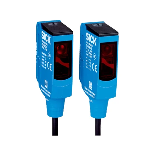
SICK 1049078 WSE9-3P3430 PNP Through-beam Sensor Pair

USD 225.00

WSE9-3P3430 offers 0–7 m red PinPoint through-beam sensing, complementary PNP outputs, 1,000 Hz switching and 120 mm PVC leads with M12 four-pin plugs.

SKU SICK-1049078 Category
SICK W9

SICK WSE9-3P3430 PNP Through-beam Sensor Pair

BrandSICK
Model IdentifierWSE9-3P3430
Official Part Number1049078

Technical Overview

The SICK WSE9-3P3430 is a through-beam photoelectric pair comprising the WS9-3D3430 sender and WE9-3P3430 receiver. Its 650 nm red PinPoint LED provides 0–7 m sensing and a separate 0–10 m maximum range, with a 25 mm spot at 1 m. Complementary PNP outputs provide light and dark states through 120 mm PVC leads with four-pin M12 plugs. No sensitivity adjustment is provided. Response is below 0.5 ms with resistive load, with 1,000 Hz switching at a 1:1 ratio. VISTAL housings, PMMA optics and M3 mounting accompany IP66/IP67/IP69K protection. Supply is 10–30 V DC, with maximum output current reduced to 50 mA at +50 °C and above; a sender-off input supports external testing.

Red PinPoint through-beam pair with 0–7 m sensing, complementary PNP outputs, sender-off input and 120 mm leads with four-pin M12 plugs.

Key Features

  • Pair: 2055828 WS9-3D3430 sender; 2055823 WE9-3P3430 receiver
  • 0–7 m sensing; 0–10 m maximum without slotted masks
  • 650 nm red PinPoint LED; Ø25 mm spot at 1 m
  • Complementary PNP outputs: Q light switching; Q̅ dark switching
  • Response <0.5 ms with resistive load; 1,000 Hz at 1:1 light/dark ratio
  • 120 mm PVC leads with M12 four-pin plugs; sender-off test input
  • No sensitivity adjustment; green power and yellow received-light indication
  • 10–30 V DC; 30 mA without load; maximum output current 50 mA at ≥+50 °C
  • VISTAL housings; PMMA optics; IP66/IP67/IP69K
  • M3 mounting holes; −40 to +60 °C operation

Detect interruptions of a direct red-light beam and provide complementary PNP states, with a sender-off input available for an external signal check.

Technical Specification Matrix

ParameterValue
Functional principleThrough-beam photoelectric sensor pair
Individual components2055828 WS9-3D3430 sender; 2055823 WE9-3P3430 receiver
Sensing range0–7 m without slotted masks
Maximum sensing range0–10 m without slotted masks
Optional slotted-mask rangesSensing / maximum: 2.0 mm mask 0–3.3 / 0–4 m; 1.5 mm mask 0–2.6 / 0–3.2 m; 1.0 mm mask 0–2 / 0–2.5 m; 0.5 mm mask 0–1 / 0–1.5 m
Light sourceVisible red PinPoint LED; 650 nm
Average LED service life100,000 h at +25 °C
Light spot sizeØ25 mm at 1 m
Additional spot sizesØ7 mm at 0 mm; Ø120 mm at 4 m; Ø200 mm at 7 m; Ø300 mm at 10 m
Sensitivity adjustmentNone
Switching outputComplementary PNP outputs
Switching modeQ=light switching; Q̅=dark switching, CD-077
Output current≤100 mA; maximum 50 mA at ambient temperature ≥+50 °C
Response time<0.5 ms signal transit time with resistive load
Switching frequency1,000 Hz at 1:1 light/dark ratio
Power supply10–30 V DC; short-circuit-protected network, maximum 8 A
Ripple<5 Vpp; remain within supply tolerances
Current consumption30 mA without load
Circuit protectionSupply and input/output reverse-polarity protection; interference suppression
Protection classIII
Connection120 mm PVC leads with M12 four-pin male connectors; do not bend below 0 °C
Sender pin assignmentCD-077: 1 BN=L+; 3 BU=M; 4 BK=Test
Receiver pin assignmentCD-077: 1 BN=L+; 2 WH=Q̅; 3 BU=M; 4 BK=Q
Test functionSender-off test input
Housing designRectangular
Housing materialVISTAL plastic
Optics materialPMMA plastic
MountingM3 holes, Ø3.1 mm; 19.2 mm slot-center spacing shown
IndicationGreen: power on; yellow: received-light-beam state
IP ratingIP66 / IP67 / IP69K
Operating temperature−40 to +60 °C
Storage temperature−40 to +75 °C
UL fileNRKH.E181493
ECOLABManufacturer certificate listed
MTTFD968 years
DCavg0%
Mission time20 years
Conductor cross-section0.14 mm²

Industrial Applications

1. Counting opaque loads between conveyor rails

A conveyor can mount the sender and receiver on opposite sides of separated opaque loads and feed PNP transitions into an external counter. The direct beam avoids reliance on light reflected by the package surface. Commissioning checks alignment, target coverage and spacing against the response below 0.5 ms, 1,000 Hz switching rating and installed sensing distance.

Problem Solved

Direct-beam interruptions give external counting electronics load-passage events, helping count separated opaque packages using an opposed sender and receiver arrangement.

Load count Direct beam Complementary PNP

2. Monitoring a break in an opaque material feed

A strip or sheet feeder can place the direct beam across a normally occupied material location. A break or exhausted feed clears the path and changes the complementary PNP states. External control times that clear condition and distinguishes sustained material loss from planned gaps, while the green power and yellow received-light indicators assist setup of the opposed optical heads.

Problem Solved

A sustained clear-path state gives external feeder monitoring a material-continuity reference, helping identify missing material before the next process step proceeds without the intended strip or sheet.

Material continuity Clear-path timing Local indication

3. Checking the sender and receiver signal chain

An external diagnostic routine can command the documented sender-off test function and observe the receiver’s complementary outputs. Suppressing emitted light provides a controlled optical-state change without inserting a load into the beam. The controller compares the resulting states with its expected sequence and records the observation as a process diagnostic. This provides an observation of the optical and electrical response during the commanded test sequence.

Problem Solved

A controlled sender-off event gives external diagnostics a repeatable signal-chain observation, helping check optical response without requiring a physical target passage.

Sender-off check External diagnostics Complementary states

Select your currency