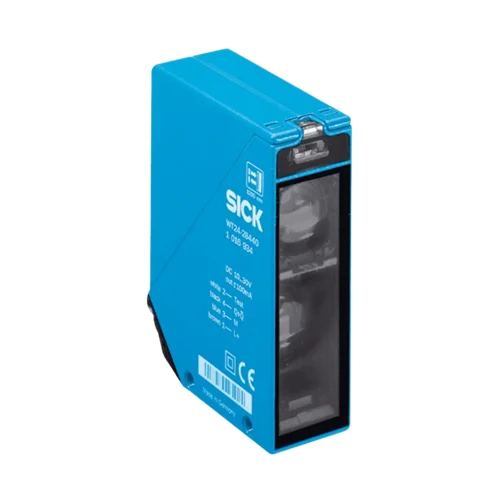
SICK 1016934 WT24-2B440 BGS Photoelectric Sensor

USD 361.66

WT24-2B440 offers background suppression, red LED sensing up to 1,200 mm on reference white, selectable NPN/PNP output, an M12 connector and IP69K.

SKU SICK-1016934 Category
SICK W24-2

SICK WT24-2B440 BGS Photoelectric Sensor

BrandSICK
Model IdentifierWT24-2B440
Official Part Number1016934

Technical Overview

The SICK WT24-2B440 is a rectangular photoelectric proximity sensor with background suppression and visible red LED illumination. Its reference-white sensing range reaches 1,200 mm, with a 40 mm light spot at that distance. A potentiometer adjusts sensing range, while separate selectors choose NPN or PNP output behavior and light or dark switching. The single output supports up to 100 mA, with a response no greater than 500 µs under resistive load and a 1,000 Hz switching rating. The four-pin M12 connection includes a sender-off test input. Zinc diecast construction, PMMA optics and IP69K protection accompany an operating temperature range of −40 to +60 °C.

Red LED background-suppression sensor with reference-white sensing up to 1,200 mm, selectable NPN/PNP and light/dark behavior, M12 connection and IP69K.

Key Features

  • Background-suppression photoelectric proximity sensing from one mounting side
  • Sensing and maximum sensing reach 1,200 mm on 90% remission reference white
  • Visible red LED; Ø40 mm light spot at 1,200 mm
  • Potentiometer sensing-range adjustment
  • One output with separate NPN/PNP and light/dark selectors
  • Response ≤500 µs with resistive load; 1,000 Hz at 1:1 light/dark ratio
  • Four-pin M12 male connector; sender-off test input TE to 0 V
  • 10–30 V DC; 50 mA consumption without load; output current ≤100 mA
  • Zinc diecast housing and PMMA optics; IP69K
  • −40 to +60 °C operation; alignment sight and received-signal indicator

Adjust the sensing boundary to distinguish a presented foreground target from a farther background, then select output behavior for the external controller.

Technical Specification Matrix

ParameterValue
Functional principlePhotoelectric proximity sensor with background suppression
Housing designRectangular
Sensing reachUp to 1,200 mm on 90% remission reference white, DIN 5033
Maximum sensing reachUp to 1,200 mm on 90% remission reference white, DIN 5033
Remission-dependent upper sensing limitsManufacturer red-light diagram: gray 18% remission 900 mm; black 6% remission 600 mm
Light sourceVisible red LED
Average LED service life100,000 h at +25 °C
Light spot sizeØ40 mm at 1,200 mm
AdjustmentSensing-range potentiometer
Switching outputSingle output; NPN or PNP selected by PNP/NPN selector
Switching modeLight/dark switching selected by separate L/D selector
Output current≤100 mA
Response time≤500 µs signal transit time with resistive load
Switching frequency1,000 Hz with 1:1 light/dark ratio
ConnectionM12 four-pin male connector
Pin assignmentCD-117: 1 BN=L+; 2 WH=Test; 3 BU=M; 4 BK=selected Q or inverted Q
Test inputSender off when TE is connected to 0 V
Power supply10–30 V DC; short-circuit-protected network, maximum 8 A
Ripple<5 Vpp; remain within supply-voltage tolerances
Current consumption50 mA without load
Circuit protectionSupply reverse-polarity protection; interference suppression; output overcurrent and short-circuit protection
Protection classII; reference voltage 50 V DC
Housing materialZinc diecast metal
Optics materialPMMA plastic
IP ratingIP69K
MountingM5 threaded mounting holes, 6 mm deep; through mounting holes
Alignment aidsAlignment sight and received-signal-strength LED indicator
Operating temperature−40 to +60 °C
Storage temperature−40 to +75 °C
MTTFD776 years
DCavg0%
Physical Weight (kg)0.33

Industrial Applications

1. Detecting a presented workpiece in front of a machine frame

An assembly station can aim the sensor at an opaque workpiece presented in front of a farther machine structure. Background suppression and potentiometer adjustment establish a foreground sensing boundary for the installed geometry. The output selectors match the required external controller behavior, with setup accounting for the actual target remission rather than applying the reference-white reach to every surface.

Problem Solved

A foreground sensing boundary reduces responses to a farther machine structure, helping sequence control identify when the intended workpiece occupies its presented position.

Foreground workpiece Background suppression Adjustable boundary

2. Counting separated raised features on a transport track

A transport track can move separated opaque features across the optical sensing location with the track surface farther behind them. A suitable sensing boundary distinguishes the passing foreground features from that background. External counting electronics interpret the selected output transitions, with the 1,000 Hz rating, 500 µs resistive-load response limit and actual feature spacing guiding the timing assessment.

Problem Solved

Foreground feature passages become electrical count events, helping external transport logic distinguish individual raised targets while suppressing a farther surface behind the sensing point.

Feature counting 1,000 Hz Selectable output

3. Checking the optical signal path during a maintenance test

During a controlled maintenance check with a target presented, external test logic can connect the TE input to 0 V to switch the sender off. The controller observes the resulting output condition and compares it with the illuminated condition under the selected light/dark logic. This provides a functional check of the ordinary optical signal path using the documented test input.

Problem Solved

The sender-off input creates a deliberate optical-state change for external maintenance logic, helping compare the illuminated and unilluminated output conditions during a controlled functional test.

Sender-off test TE to 0 V Maintenance function

Select your currency