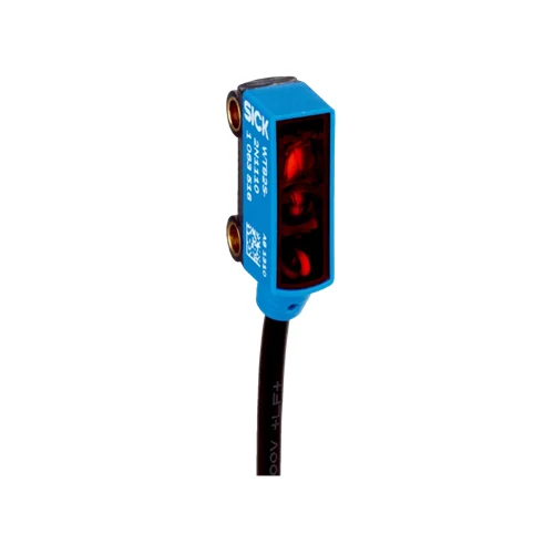
SICK 1063646 WTB2SC-2P3274A00 IO-Link Line-Spot BGS Sensor

USD 259.22

WTB2SC-2P3274A00 combines 10–70 mm reference-white sensing, a 2.2 × 9 mm red line spot at 45 mm, IO-Link V1.1, PNP output and a 200 mm M8 lead.

SKU SICK-1063646 Category
SICK W2

SICK WTB2SC-2P3274A00 IO-Link Line-Spot BGS Sensor

BrandSICK
Model IdentifierWTB2SC-2P3274A00
Official Part Number1063646

Technical Overview

The SICK WTB2SC-2P3274A00 is a background-suppression photoelectric sensor with a 640 nm red PinPoint LED and a 2.2 × 9 mm line-shaped spot at 45 mm. Reference-white sensing is 10–70 mm, maximum range is 4–90 mm and the preset distance is 45 mm. IO-Link V1.1 supports parameterization, two switching-signal process bits and device-status diagnosis. Base logics provide selectable logic, timer and inversion functions, with response times specified separately for SIO Direct, SIO Logic and full IO-Link operation. The configurable PNP device uses a 200 mm PVC lead with an M8 four-pin male connector, an IP67 ABS/PC housing and PMMA optics. Pin 4 must not be connected to another output.

Line-spot background-suppression sensor with 10–70 mm reference-white sensing, IO-Link V1.1, Base logics, configurable PNP signaling and M8 four-pin lead.

Key Features

  • 10–70 mm sensing; 4–90 mm maximum on 90% remission white; preset 45 mm
  • 640 nm red PinPoint LED; line spot 2.2 × 9 mm at 45 mm
  • IO-Link V1.1, COM2 at 38.4 kBaud; 2.3 ms communication cycle
  • 16-bit process data: bit 0=QL1, bit 1=QL2, remaining bits empty
  • PNP output and light/dark behavior parameterizable through IO-Link
  • Pin 2 configurable as external/teach/sender-off input or detection/logic output
  • Base logics: Direct, AND, OR, WINDOW, hysteresis, timers and inversion
  • Mode-specific response: SIO Direct 300–450 µs; SIO Logic 500–600 µs; IOL 500–900 µs
  • 10–30 V DC; ≤50 mA output; 200 mm PVC lead with M8 four-pin male connector
  • ABS/PC housing, PMMA optics, IP67 and −25 to +50 °C operation

Use a red line spot for the documented target presentations, then configure switching logic and timing through IO-Link to deliver the required machine event.

Technical Specification Matrix

ParameterValue
Functional principlePhotoelectric proximity sensor with background suppression
Sensing range10–70 mm on 90% remission reference white, DIN 5033
Maximum sensing range4–90 mm on 90% remission reference white, DIN 5033
Preset sensing distance45 mm
Target-dependent ranges18% gray: sensing 10–70 mm, maximum 5–80 mm; 6% black: sensing 10–70 mm, maximum 6–70 mm; 1% ultra-black: sensing 15–40 mm, maximum 8–40 mm, manufacturer range diagram
Light source640 nm visible red PinPoint LED
Average LED service life100,000 h at +25 °C
Light spot sizeLine-shaped, 2.2 × 9 mm at 45 mm
Spot size by distanceVertical × horizontal: at 0 mm 3.5 × 3.8 mm; 10 mm 3.0 × 5.2; 20 mm 3.3 × 6.4; 30 mm 1.8 × 7.4; 40 mm 2.0 × 8.6; 60 mm 4.4 × 10.5; 80 mm 6.5 × 12.8; 100 mm 9.0 × 14.5, all spot values in mm
Documented target rolesSmall, perforated, uneven or shiny objects; film-wrapped objects; objects with position tolerances
AdjustmentIO-Link
Switching outputPNP, parameterizable via IO-Link; pin 4 must not be connected to another output
Switching modeProgrammable light/dark switching through IO-Link
Pin 2 functionsExternal input; teach-in input; sender-off input; detection output; logic output
Output current≤50 mA
General response time<0.5 ms with resistive load, manufacturer mechanics table
Configured pin 2 timingQ̅ on pin 2, if configured in software: 300–450 µs response with resistive load; 150 µs repeatability; 1,000 Hz at 1:1 light/dark ratio
General switching frequency1,000 Hz, manufacturer mechanics table
IO-LinkV1.1; COM2, 38.4 kBaud; cycle time 2.3 ms
Process data16 bit: bit 0=QL1; bit 1=QL2; bits 2–15 empty
IO-Link identifiersVendorID 26; DeviceID 0x800121 (8388897)
Master compatibilityPort type A; SIO mode supported
Smart TaskBase logics
Logic functionsDirect; AND; OR; WINDOW; hysteresis
Timer functionsDeactivated; switch-on delay; off delay; ON and OFF delay; impulse (one shot)
InverterSupported
Mode-specific switching frequencySIO Direct 1,000 Hz; SIO Logic 1,000 Hz; full IOL 900 Hz
Mode-specific response timeSIO Direct 300–450 µs; SIO Logic 500–600 µs; full IOL 500–900 µs
Mode-specific repeatabilitySIO Direct 150 µs; SIO Logic 150 µs; full IOL 400 µs
Operating-mode definitionsSIO Direct: no IO-Link communication and internal logic/timers set to direct/deactivated; SIO Logic: no IO-Link communication, internal logic/timing and Automation Functions used; IOL: full IO-Link communication with logic/timing and Automation Functions
Logic switching signalsQL1 and QL2 switching outputs
DiagnosisDevice status
Power supply10–30 V DC, limit values
Ripple<5 Vpp; remain within supply-voltage tolerances
Current consumption20 mA without load
Connection200 mm PVC cable with M8 four-pin male connector; do not bend below 0 °C
Conductor cross-section0.09 mm²
Cable diameterØ3 mm
Pin assignmentCD-367: 1 BN=L+; 4 BK=QL1/C; 2 WH=MF; 3 BU=M
Circuit protectionSupply and output reverse-polarity protection; output overcurrent and short-circuit protection
Protection classIII
Housing designRectangular
Housing materialABS/PC
Optics materialPMMA
IP ratingIP67
Operating temperature−25 to +50 °C
Storage temperature−40 to +75 °C
MountingØ3.2 mm holes; 15 mm center spacing
IndicatorsGreen: supply voltage; yellow: received-light-beam status
UL fileNRKH.E181493
MTTFD1,547 years
DCavg0%

Industrial Applications

1. Detecting a perforated component at a presentation station

A presentation station can orient the red line spot across a representative perforated component at a controlled distance. The manufacturer lists perforated objects among this model’s detection roles. Background suppression and IO-Link adjustment establish the target condition, while external sequencing reads the configured PNP output after presentation. Setup assesses the actual hole pattern, remission and placement tolerance against the line-spot geometry.

Problem Solved

The line-shaped optical observation provides a presence condition for external sequencing on a perforated target, helping distinguish the expected component presentation from an empty position.

Perforated targets Line spot Background suppression

2. Changing the detection settings with an assembly recipe

An assembly station that changes component presentations can use an IO-Link master to set the sensor parameters alongside the selected machine recipe. Programmable light/dark behavior and configurable pin 2 functions adapt the electrical event to the process. External changeover logic coordinates the update while the machine is in its setup state and verifies the new presentation before operation resumes.

Problem Solved

Remote parameter access lets external changeover logic align sensing behavior with the selected assembly recipe, reducing repeated local adjustment when the target presentation changes.

Recipe settings IO-Link V1.1 Configurable pin 2

3. Delaying a signal until a presented object remains detected

A transfer position can use the sensor’s switch-on delay to require a detected object to remain present before issuing the configured event. Base logics and inversion establish the useful signal behavior, and external sequencing then evaluates that output. The timing design uses the SIO Logic or full IO-Link response and frequency for the selected operating mode rather than the faster SIO Direct figures.

Problem Solved

An internal switch-on delay creates a persistence-based detection event, helping external transfer sequencing distinguish a sustained presentation from a brief passage through the optical field.

Switch-on delay Base logics Mode-specific timing
Select your currency