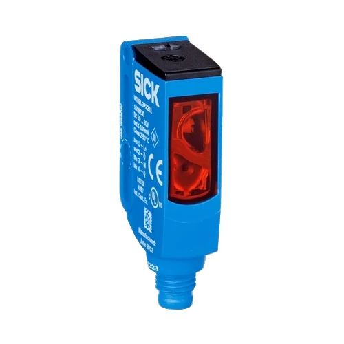
SICK 1062523 WTB9L-3N2261 NPN Laser BGS Sensor

USD 236.60

WTB9L-3N2261 offers 25–300 mm reference-white sensing, a 1 mm laser spot at 170 mm, complementary NPN outputs, five-turn adjustment and M8 connection.

SKU SICK-1062523 Category
SICK W9

SICK WTB9L-3N2261 NPN Laser Background-Suppression Sensor

BrandSICK
Model IdentifierWTB9L-3N2261
Official Part Number1062523

Technical Overview

The SICK WTB9L-3N2261 is a laser photoelectric proximity sensor with background suppression and complementary NPN outputs. Its 650 nm Class 1 red laser forms a 1 mm spot at 170 mm, supporting small-object detection. Sensing and maximum sensing range are 25–300 mm on 90% remission reference white, with a five-turn potentiometer setting the sensing condition. Response is no more than 0.5 ms with resistive load, and switching frequency is 1,000 Hz at a 1:1 light/dark ratio. The four-pin M8 device uses 10–30 V DC, a VISTAL housing and PMMA optics with IP66/IP67/IP69K protection. Normal operation spans −10 to +50 °C; extended operation has specified supply, load and start-up conditions.

Class 1 laser BGS sensor with 25–300 mm reference-white range, complementary NPN outputs, five-turn adjustment and four-pin M8 connection.

Key Features

  • Background suppression; manufacturer special application: detecting small objects
  • 25–300 mm sensing and maximum range on 90% remission reference white
  • 650 nm visible red Class 1 laser; Ø1 mm spot at 170 mm
  • Five-turn sensing-range potentiometer
  • Complementary NPN outputs; Q light switching and Q̅ dark switching
  • Response ≤0.5 ms with resistive load; 1,000 Hz at 1:1 light/dark ratio
  • 10–30 V DC; 30 mA without load; four-pin M8 male connector
  • VISTAL housing; PMMA optics; IP66/IP67/IP69K
  • M3 mounting; yellow received-light and green power LEDs
  • Normal −10 to +50 °C; extended −30 to +55 °C only under documented conditions

Place a small laser spot on the target and use background suppression with complementary NPN signals for external inspection or motion-event control.

Technical Specification Matrix

ParameterValue
Functional principlePhotoelectric proximity sensor with background suppression
Sensing range25–300 mm on 90% remission reference white, DIN 5033
Maximum sensing range25–300 mm on 90% remission reference white, DIN 5033
Typical target-dependent maximum rangesBlack 6% remission: 25–170 mm; gray 18%: 25–250 mm; white 90%: 25–300 mm
Light sourceVisible red laser; 650 nm
Laser classClass 1; IEC 60825-1 and CDRH 21 CFR 1040.10/1040.11
Average laser service life50,000 h at TU = +25 °C
Light spot sizeØ1 mm at 170 mm
AdjustmentSensing-range potentiometer, five turns
Manufacturer special applicationDetecting small objects
Switching outputNPN, complementary
Switching modeLight/dark switching; Q=light switching, Q̅=dark switching
Output current≤100 mA; at and above +50 °C in extended operation, maximum 50 mA
Response time≤0.5 ms with resistive load
Switching frequency1,000 Hz at 1:1 light/dark ratio
ConnectionM8 four-pin male connector
Pin assignmentCD-083: 1 BN=L+; 2 WH=Q̅; 3 BU=M; 4 BK=Q
Power supply10–30 V DC; short-circuit-protected network, max. 8 A
Ripple<5 Vpp; remain within supply-voltage limits
Current consumption30 mA without load
Circuit protectionA: supply reverse-polarity protection; B: input/output reverse-polarity protection; C: interference suppression
Protection classIII
Housing designRectangular
Housing materialVISTAL plastic
Optics materialPMMA plastic
IP ratingIP66 / IP67 / IP69K
MountingM3 mounting hole; Ø3.1 mm
IndicationYellow LED: received-light status; green LED: power on
Operating temperature−10 to +50 °C
Extended operating temperature−30 to +55 °C under manufacturer supply/load and cold-operation conditions
Extended-temperature electrical limitsAt and above +50 °C: supply voltage ≤24 V and load current ≤50 mA
Cold-operation conditionBelow −10 °C only after switching on above −10 °C, cooling down and maintaining supply continuously; switching on below −10 °C is not permitted
Storage temperature−30 to +70 °C
MTTFD423 years; EN ISO 13849-1, parts-count calculation
DCavg0%
UL fileNRKH.E181493
ECOLABManufacturer certificate listed
Physical Weight (kg)0.013

Industrial Applications

1. Checking a small component in a presentation fixture

A fixture can present a small opaque component near the adjusted sensing point and use a complementary NPN signal for external inspection logic. The 1 mm laser spot at 170 mm helps place the optical reference, while background suppression separates the intended target from more distant surfaces. Commissioning verifies actual component coverage, remission, background position and the selected working distance.

Problem Solved

A defined optical sensing point gives external inspection logic a component-presentation reference, helping identify an omitted or displaced target while limiting responses from more distant fixture surfaces.

Small component Laser spot Background suppression

2. Counting separated features on a moving carrier

A carrier can move separated opaque features through the adjusted sensing point and feed NPN transitions to external counting electronics. The controller counts passages after commissioning verifies feature coverage, target reflectance and spacing. Motion timing accounts for the ≤0.5 ms resistive-load response and 1,000 Hz rating, while the selected sensing distance respects the target-dependent range.

Problem Solved

Repeated optical transitions give external counting logic a passage reference for carrier features, helping register motion events using actual target movement through the installed sensing point.

Feature counting 1,000 Hz Optical transition

3. Comparing complementary signals during fixture diagnostics

A fixture can connect Q and complementary Q̅ to two ordinary controller inputs and compare their settled states during a commanded presentation cycle. The NPN light/dark outputs provide opposing signals from the same optical condition. External diagnostic logic checks the expected relationship after transitions settle and records inconsistent input observations for maintenance, without treating this comparison as a safety function.

Problem Solved

Complementary observations give external maintenance logic a basis for identifying an unexpected input relationship, helping separate a normal optical transition from a wiring or input-reading inconsistency.

Complementary outputs Fixture diagnostics External comparison

Select your currency