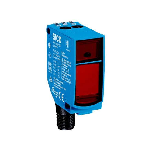
SICK 1072626 WTT12L-B2538 Time-of-Flight Sensor

USD 425.62

WTT12L-B2538: 2,500 mm upper sensing limit, two distance thresholds, push-pull PNP/NPN, Class 1 red laser and M12 connection.

SKU SICK-1072626 Category
SICK WTT12 PowerProx

SICK WTT12L-B2538 Time-of-Flight Sensor

BrandSICK
Model IdentifierWTT12L-B2538
Official Part Number1072626

Technical Overview

The SICK WTT12L-B2538 is a visible-red-laser photoelectric proximity sensor using optical time-of-flight with background suppression. Its adjustable sensing range is 100–2,500 mm, while the maximum range is 50–2,500 mm on 6–90% remission targets. The 658 nm Class 1 source produces a 14 mm spot at 2,500 mm. Two four-turn potentiometers set separate thresholds for Q1 and Q2 push-pull outputs. Response is no more than 0.5 ms with a resistive load, with 1,000 Hz switching at a 1:1 light/dark ratio. The IP67 VISTAL housing has PMMA optics and an M12 five-pin male connector. The L/D light/dark switching input supports external machine integration.

Class 1 red-laser background-suppression sensor with 100–2,500 mm adjustable sensing, two thresholds, push-pull PNP/NPN and an M12 five-pin male connector.

Key Features

  • Optical time-of-flight proximity sensing with background suppression
  • 100–2,500 mm adjustable sensing range
  • 50–2,500 mm maximum range on 6–90% remission targets
  • 658 nm visible red Class 1 laser; Ø14 mm spot at 2,500 mm
  • 2 four-turn potentiometers; two switching thresholds
  • Two push-pull PNP/NPN outputs, Q1 and Q2; two switching thresholds
  • ≤0.5 ms resistive-load response; 1,000 Hz at 1:1 light/dark ratio
  • M12 five-pin male connector; L/D light/dark switching input
  • 10–30 V DC; 70 mA without load at 24 V; <300 ms initialization
  • VISTAL housing and PMMA optics; IP67; −35 to +50 °C with current derating

Set two distance thresholds with four-turn adjustment and report separate target-distance conditions to external control.

Technical Specification Matrix

ParameterValue
Functional principlePhotoelectric proximity sensing with background suppression and optical time-of-flight
Housing designRectangular
Sensing range100–2,500 mm, adjustable
Maximum sensing range50–2,500 mm on 6–90% remission targets, based on standard white DIN 5033
Background separationRequired object-to-background distance depends on target distance and remission, as shown in the manufacturer characteristic curve
Light sourceVisible red laser; 658 nm
Laser classClass 1, IEC 60825-1 / CDRH 21 CFR 1040.10 and 1040.11
Average laser service life100,000 h at +25 °C
Light spot sizeØ14 mm at 2,500 mm
Adjustment2 four-turn sensing-range potentiometers
Digital outputsTwo push-pull PNP/NPN outputs, Q1 and Q2; two switching thresholds
Switching modeLight switching
Control inputL/D light/dark switching input
Output current≤100 mA; maximum 50 mA from ambient +45 °C
Response time≤0.5 ms, signal transit time with resistive load
Switching frequency1,000 Hz at 1:1 light/dark ratio
Power supply10–30 V DC; short-circuit-protected network, maximum 8 A
Ripple<5 Vpp; remain within supply-voltage tolerances
Current consumption70 mA without load at 24 V
Circuit protectionSupply, input and output reverse-polarity protection; interference suppression
Protection classIII
Initialization time<300 ms
Warm-up time<15 min; warm-up necessary below −10 °C
ConnectionM12 five-pin male connector
Housing materialVISTAL plastic
Optics materialPMMA plastic
IP ratingIP67
Operating temperature−35 to +50 °C; output current limited to 50 mA from +45 °C
Storage temperature−40 to +70 °C
Mounting holesØ4.2 mm
IndicationGreen power-on LED; yellow received-light indicators
MTTFD133 years
DCavg0%
Mission time20 years
Pin assignmentCD-286: 1 BN=L+; 2 WH=Q2; 3 BU=M; 4 BK=Q1; 5 GY=L/D
Physical Weight (kg)0.048

Industrial Applications

1. Counting separated opaque loads on a conveyor

A conveyor can present separated opaque loads within the adjusted sensing zone and send push-pull transitions to external counting logic. Optical time-of-flight with background suppression separates the presented load from a farther background when the installed geometry provides the required clearance. Commissioning evaluates actual remission, target spacing and speed against the 1,000 Hz switching rating and 0.5 ms resistive-load response.

Problem Solved

Load-passage transitions give external counting logic a discrete event stream, helping track separated articles from one mounting side while using an adjusted background-suppression zone.

Conveyor counting 1,000 Hz Background suppression

2. Classifying a presented load by two height thresholds

A load-inspection station can aim the sensor downward at a carrier and set its two sensing thresholds around selected surface-distance limits. External inspection logic evaluates the Q1 and Q2 pattern after the carrier settles, interpreting distance relative to the fixed sensor as a height condition. Setup accounts for actual surface remission, background clearance and the manufacturer’s distance-dependent repeatability curve.

Problem Solved

Two discrete distance conditions give external inspection logic a basis for separating load-height classes, helping identify a presented surface outside the selected process band.

Load-height classification Two thresholds External pattern logic

3. Reporting two fill thresholds in an opaque-material hopper

A hopper can present an opaque material surface toward a sensor mounted at a fixed reference above it. Two potentiometers set separate distance thresholds corresponding to selected fill conditions. External replenishment logic evaluates the Q1 and Q2 states as the surface moves, with setup accounting for surface shape, remission, required background separation and the documented switching response.

Problem Solved

Separate surface-distance conditions supply external replenishment logic with two fill references, helping distinguish the selected material bands without requiring a continuous analog level signal.

Hopper fill thresholds Two switching outputs External replenishment

Select your currency