RM 1,402.00 – RM 1,865.00Price range: RM 1,402.00 through RM 1,865.00
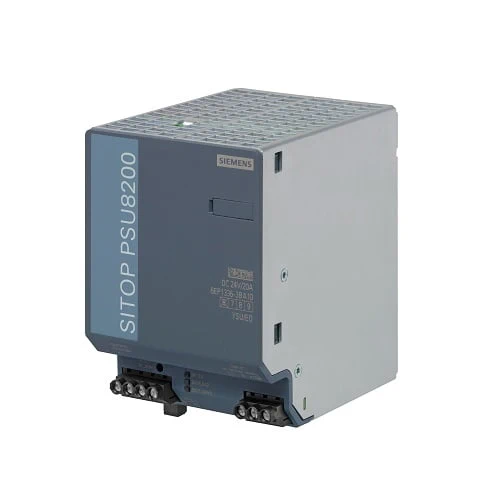
| Article number | 6EP1336-3BA10 |
| Product | SITOP PSU8200 |
| Power supply, type | 24 V/20 A |
| Input | |
| type of the power supply network | 1-phase and 2-phase AC or DC |
| supply voltage at AC | |
| ● minimum rated value | 120 V |
| ● maximum rated value | 230 V |
| ● initial value | 85 V; Derating of temperature necessary down to 50 °C at Vin < 100 V AC or DC |
| ● full-scale value | 275 V |
| supply voltage | |
| ● 1 at AC rated value | |
| ● 2 at AC rated value | |
| ● at DC | 110 … 220 V |
| input voltage | |
| ● 1 at AC | |
| ● 2 at AC | |
| ● at DC | 88 … 350 V |
| design of input wide range input | Yes |
| operating condition of the mains buffering | at Vin = 230 V |
| buffering time for rated value of the output current in the event of power failure minimum | 20 ms |
| operating condition of the mains buffering | at Vin = 230 V |
| line frequency | |
| ● 1 rated value | 50 Hz |
| ● 2 rated value | 60 Hz |
| line frequency | 45 … 65 Hz |
| input current | |
| ● at rated input voltage 120 V | 4.6 A |
| ● at rated input voltage 230 V | 2.5 A |
| current limitation of inrush current at 25 °C maximum | 20 A |
| I2t value maximum | 5 A²·s |
| fuse protection type | Yes |
| ● in the feeder | Recommended miniature circuit breaker at 1-phase operation: 10 A characteristic C; required at 2-phase operation: circuit breaker 2-pole connected or circuit breaker 3RV2711-1HD10 (UL 489) at 120 V or 3RV2711-1ED10 (UL 489) at 230 V |
| Output | |
| voltage curve at output | Controlled, isolated DC voltage |
| output voltage at DC rated value | 24 V |
| output voltage | |
| ● at output 1 at DC rated value | 24 V |
| relative overall tolerance of the voltage | 3 % |
| relative control precision of the output voltage | |
| ● on slow fluctuation of input voltage | 0.1 % |
| ● on slow fluctuation of ohm loading | 0.3 % |
| residual ripple | |
| ● maximum | 100 mV |
| ● typical | 80 mV |
| voltage peak | |
| ● maximum | 200 mV |
| ● typical | 100 mV |
| adjustable output voltage | 24 … 28.8 V |
| product function output voltage adjustable | Yes |
| type of output voltage setting | via potentiometer |
| display version for normal operation | Green LED for 24 V OK |
| type of signal at output | Relay contact (NO contact, rating 60 V DC/ 0.3 A) for “24 V OK” |
| behavior of the output voltage when switching on | No overshoot of Vout (soft start) |
| response delay maximum | 1.5 s |
| voltage increase time of the output voltage | |
| ● typical | 50 ms |
| output current | |
| ● rated value | 20 A |
| ● rated range | 0 … 20 A; +60 … +70 °C: Derating 3%/K |
| supplied active power typical | 480 W |
| short-term overload current | |
| ● on short-circuiting during the start-up typical | |
| ● at short-circuit during operation typical | 60 A |
| duration of overloading capability for excess current | |
| ● on short-circuiting during the start-up | |
| ● at short-circuit during operation | 25 ms |
| constant overload current | |
| ● on short-circuiting during the start-up typical | 30 A |
| product feature | |
| ● bridging of equipment | Yes; switchable characteristic |
| number of parallel-switched equipment resources for increasing the power | 2 |
| Efficiency | |
| efficiency in percent | 93 % |
| power loss [W] | |
| ● at rated output voltage for rated value of the output current typical | 42 W |
| ● during no-load operation maximum | |
| Closed-loop control | |
| relative control precision of the output voltage with rapid fluctuation of the input voltage by +/- 15% typical | 0.5 % |
| relative control precision of the output voltage load step of resistive load 50/100/50 % typical | 1 % |
| setting time | |
| ● load step 50 to 100% typical | 1 ms |
| ● load step 100 to 50% typical | 1 ms |
| relative control precision of the output voltage at load step of resistive load 10/90/10 % typical | |
| setting time | |
| ● load step 10 to 90% typical | |
| ● load step 90 to 10% typical | |
| ● maximum | 5 ms |
| Protection and monitoring | |
| design of the overvoltage protection | < 33 V |
| ● typical | 21.5 A |
| property of the output short-circuit proof | Yes |
| design of short-circuit protection | Alternatively, constant current characteristic approx. 23 A or latching shutdown |
| enduring short circuit current RMS value | |
| ● typical | 23 A |
| overcurrent overload capability in normal operation | overload capability 150 % Iout rated up to 5 s/min |
| display version for overload and short circuit | LED yellow for “overload”, LED red for “latching shutdown” |
| Safety | |
| galvanic isolation between input and output | Yes |
| galvanic isolation | Safety extra-low output voltage Uout acc. to EN 60950-1 and EN 50178 |
| operating resource protection class | Class I |
| leakage current | |
| ● maximum | 3.5 mA |
| ● typical | 1 mA |
| protection class IP | IP20 |
| Approvals | |
| certificate of suitability | |
| ● CE marking | Yes |
| ● UL approval | Yes; cULus-Listed (UL 508, CSA C22.2 No. 107.1), File E197259; cCSAus (CSA C22.2 No. 60950-1, UL 60950-1) |
| ● CSA approval | Yes; cULus-Listed (UL 508, CSA C22.2 No. 107.1), File E197259; cCSAus (CSA C22.2 No. 60950-1, UL 60950-1) |
| ● cCSAus, Class 1, Division 2 | No |
| ● ATEX | No |
| certificate of suitability | |
| ● IECEx | No |
| ● NEC Class 2 | No |
| ● ULhazloc approval | No |
| ● FM registration | No |
| type of certification CB-certificate | Yes |
| certificate of suitability | |
| ● EAC approval | Yes |
| certificate of suitability shipbuilding approval | Yes |
| shipbuilding approval | ABS, DNV GL |
| Marine classification association | |
| ● American Bureau of Shipping Europe Ltd. (ABS) | Yes |
| ● French marine classification society (BV) | No |
| ● DNV GL | Yes |
| ● Lloyds Register of Shipping (LRS) | No |
| ● Nippon Kaiji Kyokai (NK) | No |
| EMC | |
| standard | |
| ● for emitted interference | EN 55022 Class B |
| ● for mains harmonics limitation | EN 61000-3-2 |
| ● for interference immunity | EN 61000-6-2 |
| environmental conditions | |
| ambient temperature | |
| ● during operation | -25 … +70 °C; With natural convection; startup tested starting from -40 °C nominal voltage |
| ● during transport | -40 … +85 °C |
| ● during storage | -40 … +85 °C |
| environmental category according to IEC 60721 | Climate class 3K3, 5 … 95% no condensation |
| Mechanics | |
| type of electrical connection | screw-type terminals |
| ● at input | L, N, PE: 1 screw terminal each for 0.2 … 4 mm² single-core/finely stranded |
| ● at output | +, -: 2 screw terminals each for 0.2 … 4 mm² |
| ● for auxiliary contacts | 13, 14 (alarm signal): 1 screw terminal each for 0.14 … 1.5 mm² |
| width of the enclosure | 90 mm |
| height of the enclosure | 125 mm |
| depth of the enclosure | 125 mm |
| required spacing | |
| ● top | 50 mm |
| ● bottom | 50 mm |
| ● left | 0 mm |
| ● right | 0 mm |
| net weight | 1.2 kg |
| product feature of the enclosure housing can be lined up | Yes |
| fastening method | Snaps onto DIN rail EN 60715 35×7.5/15 |
| electrical accessories | Buffer module |
| mechanical accessories | Device identification label 20 mm × 7 mm, TI-grey 3RT2900-1SB20 |
| MTBF at 40 °C | 667 048 h |
| other information | Specifications at rated input voltage and ambient temperature +25 °C (unless otherwise specified) |
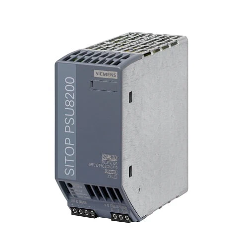
| Article number | 6EP3334-8SB00-0AY0 |
| Product | SITOP PSU8200 |
| Input | |
| type of the power supply network | 1-phase AC |
| supply voltage at AC | |
| ● initial value | Automatic range selection |
| supply voltage | |
| ● 1 at AC rated value | 120 V |
| ● 2 at AC rated value | 230 V |
| input voltage | |
| ● 1 at AC | 85 … 132 V |
| ● 2 at AC | 170 … 264 V |
| design of input wide range input | No |
| operating condition of the mains buffering | at Vin = 120/230 V |
| buffering time for rated value of the output current in the | 35 ms |
| event of power failure minimum | |
| operating condition of the mains buffering | at Vin = 120/230 V |
| line frequency | |
| ● 1 rated value | 50 Hz |
| ● 2 rated value | 60 Hz |
| line frequency | 47 … 63 Hz |
| input current | |
| ● at rated input voltage 120 V | 4A |
| ● at rated input voltage 230 V | 1.9A |
| current limitation of inrush current at 25 °C maximum | 10A |
| I2t value maximum | 0.3 A²·s |
| fuse protection type | T 6.3 A (not accessible) |
| ● in the feeder | Recommended miniature circuit breaker at 1-phase operation: from 6 A (10 A) characteristic C (B); required at 2-phase operation: circuit breaker 2-pole connected or circuit breaker 3RV2011-1EA10 (setting 3.8 A) or 3RV2711-1ED10 (UL 489) at 230 V; 3RV2011-1DA10 (setting 3 A) or 3RV2711-1DD10 (UL 489) at 400/500 V |
| Output | |
| voltage curve at output | Controlled, isolated DC voltage |
| output voltage at DC rated value | 24v |
| output voltage | |
| ● at output 1 at DC rated value | 24V |
| relative overall tolerance of the voltage | 3% |
| relative control precision of the output voltage | |
| ● on slow fluctuation of input voltage | 0.1% |
| ● on slow fluctuation of ohm loading | 0.3% |
| residual ripple | |
| ● maximum | 50 mV |
| voltage peak | |
| ● maximum | 200 mV |
| adjustable output voltage | 24 … 28.8 V |
| product function output voltage adjustable | Yes |
| type of output voltage setting | via potentiometer; max. 240 W |
| display version for normal operation | Green LED for 24 V OK |
| type of signal at output | Relay contact (NO contact, rating 60 V DC/ 0.3 A) for “24 V OK” |
| behavior of the output voltage when switching on | Overshoot of Vout approx. 3 % |
| response delay maximum | 1.5 s |
| voltage increase time of the output voltage | |
| ● typical | 70 ms |
| output current | |
| ● rated value | 10A |
| ● rated range | 0 … 10 A; +60 … +70 °C: Derating 2%/K; as of Ua>24 V: 4% [Ia]/V [Ua]; at Ue<100 V/<200 V: 80% Ia rated |
| supplied active power typical | 240 W |
| short-term overload current | |
| ● at short-circuit during operation typical | 30 A |
| duration of overloading capability for excess current | |
| ● at short-circuit during operation | 25 ms |
| constant overload current | |
| ● on short-circuiting during the start-up typical product feature | 12 A |
| ● bridging of equipment | Yes; switchable characteristic |
| number of parallel-switched equipment resources for increasing the power | 2 |
| Efficiency | |
| efficiency in percent | 94% |
| power loss [W] | |
| ● at rated output voltage for rated value of the output current typical | 18 W |
| ● during no-load operation maximum | 1.5 W |
| Closed-loop control | |
| relative control precision of the output voltage with rapid fluctuation of the input voltage by +/- 15% typical |
0.1% |
| relative control precision of the output voltage load step of | 4% |
| resistive load 50/100/50 % typical | |
| setting time | |
| ● load step 50 to 100% typical | 0.25 ms |
| ● load step 100 to 50% typical | 0.5 ms |
| relative control precision of the output voltage at load step | 4% |
| of resistive load 10/90/10 % typical | |
| setting time | |
| ● load step 10 to 90% typical | 0.25 ms |
| ● load step 90 to 10% typical | 0.5 ms |
| ● maximum | 1 ms |
| Protection and monitoring | |
| design of the overvoltage protection | < 33 V |
| ● typical | 12 A |
| property of the output short-circuit proof | Yes |
| design of short-circuit protection | Alternatively, constant current characteristic approx. 12 A or latching shutdown |
| enduring short circuit current RMS value | |
| ● typical | 12 A |
| overcurrent overload capability in normal operation | overload capability 150 % Iout rated up to 5 s/min |
| display version for overload and short circuit | LED yellow for “overload”, LED red for “latching shutdown” |
| Safety | |
| galvanic isolation between input and output | Yes |
| galvanic isolation | Safety extra-low output voltage Uout acc. to EN 60950-1 and EN 50178 |
| operating resource protection class | Class I |
| leakage current | |
| ● maximum | 3.4 mA |
| ● typical | 1 mA |
| protection class IP | IP20 |
| Approvals | |
| certificate of suitability | |
| ● CE marking | Yes |
| ● UL approval | Yes; cULus-Listed (UL 508, CSA C22.2 No. 107.1), File E197259; cCSAus (CSA C22.2 No. 60950-1, UL 60950-1) |
| ● CSA approval | Yes; cULus-Listed (UL 508, CSA C22.2 No. 107.1), File E197259; cCSAus (CSA C22.2 No. 60950-1, UL 60950-1) |
| ● cCSAus, Class 1, Division 2 | No |
| ● ATEX | No |
| certificate of suitability | |
| ● IECEx | No |
| ● NEC Class 2 | No |
| ● ULhazloc approval | No |
| ● FM registration | No |
| type of certification CB-certificate | Yes |
| certificate of suitability | |
| ● EAC approval | Yes |
| certificate of suitability shipbuilding approval | Yes |
| shipbuilding approval | ABS, DNV GL |
| Marine classification association | |
| ● American Bureau of Shipping Europe Ltd. (ABS) | Yes |
| ● French marine classification society (BV) | No |
| ● DNV GL | Yes |
| ● Lloyds Register of Shipping (LRS) | No |
| ● Nippon Kaiji Kyokai (NK) | No |
| EMC | |
| standard | |
| ● for emitted interference | EN 55022 Class B |
| ● for mains harmonics limitation | EN 61000-3-2 |
| ● for interference immunity | EN 61000-6-2 |
| environmental conditions | |
| ambient temperature | |
| ● during operation | -25 … +70 °C; With natural convection; startup tested starting from -40 °C nominal voltage |
| ● during transport | -40 … +85 °C |
| ● during storage | -40 … +85 °C |
| environmental category according to IEC 60721 | Climate class 3K3, 5 … 95% no condensation |
| Mechanics | |
| type of electrical connection | screw-type terminals |
| ● at input | L, N, PE: 1 screw terminal each for 0.2 … 2.5 mm² single-core/finely stranded |
| ● at output | +, -: 2 screw terminals each for 0.2 … 2.5 mm² |
| 13, 14 (alarm signal): 1 screw terminal each for 0.14 … 1.5 mm²; 15, 16 (Remote): 1 screw terminal each for 0.14 … 1.5 mm² |
|
| width of the enclosure | 55 mm |
| height of the enclosure | 125 mm |
| depth of the enclosure | 125 mm |
| required spacing | |
| ● top | 50 mm |
| ● bottom | 50 mm |
| ● left | 0 mm |
| ● right | 0 mm |
| net weight | 1kg |
| product feature of the enclosure housing can be lined up | Yes |
| fastening method | Snaps onto DIN rail EN 60715 35×7.5/15 |
| electrical accessories | Buffer module |
| mechanical accessories | Device identification label 20 mm × 7 mm, TI-grey 3RT2900-1SB20 |
| MTBF at 40 °C | 1 292 102 h |
| other information | Specifications at rated input voltage and ambient temperature +25 °C (unless otherwise specified) |