Sale!

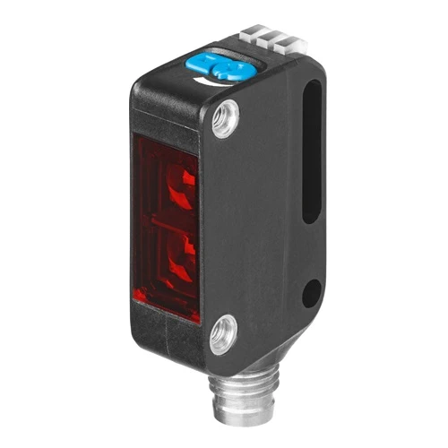
Festo 8075670 Laser Diffuse Sensor, IO-Link, 7–300 mm

Original price was: USD 119.08.Current price is: USD 102.96.

Red-laser sensor with 7–300 mm working range, 1650 Hz push-pull switching, three-pin M8 connector, teach-in adjustment and IP65/IP67/IP69K protection.

SKU Festo-8075670 Category
Festo Optical Sensors

Festo SOOE-BS-L-PNLK-T Laser Diffuse Sensor with Background Suppression

BrandFesto
Model IdentifierSOOE-BS-L-PNLK-T
Official Part Number8075670

Technical Overview

The Festo SOOE-BS-L-PNLK-T is a red-laser diffuse sensor with background suppression, identified as background clipping in its exact-part datasheet. Its 7–300 mm working range is referenced to a 90% white, 100 × 100 mm standard target; the adjustment range is 25–300 mm. The push-pull output supports switchable PNP light/NPN dark switching at up to 1650 Hz and 100 mA. IO-Link Device V1.1 provides COM2 communication, teach-channel functions and timer configuration. A three-pin A-coded M8 connector supplies the 10–30 V DC device. The 10 g sensor has M3 through-hole mounting, IP65/IP67/IP69K protection and a −40 to +60 °C ambient range.

Red-laser diffuse sensor with background suppression, 7–300 mm working range, 1650 Hz push-pull output, IO-Link and three-pin M8 connection.

Key Features

  • Red-laser diffuse detection with background suppression; Class 1 laser
  • 7–300 mm working range with 90% white 100 × 100 mm reference target
  • 25–300 mm setting range via IO-Link, potentiometer or teach-in
  • 1 mm maximum light spot at 200 mm and 2 mm minimum object diameter
  • 45% maximum black-white difference and 18 mm hysteresis
  • 1650 Hz maximum switching frequency and 100 mA maximum output current
  • Push-pull output with PNP light/NPN dark switching
  • IO-Link Device V1.1, COM2 and 2.3 ms minimum cycle time
  • 10–30 V DC supply through three-pin A-coded M8 connector
  • 10 g product weight with IP65/IP67/IP69K protection

Detect foreground targets with a red laser and background suppression, using a 1 mm maximum light spot at 200 mm and IO-Link setup.

Technical Specification Matrix

ParameterValue
DesignBlock design
Conforms to standardEN 60947-5-2
ApprovalRCM; c UL us - Listed (Oil)
CE mark (see declaration of conformity)To EU EMC Directive; In accordance with EU RoHS Directive
UKCA marking (see declaration of conformity)To UK instructions for EMC; To UK RoHS instructions
Certificate issuing authorityUL E232949
Note on materialsRoHS compliant
Measuring principleOptoelectronic
Detection methodDiffuse sensor with background clipping
Type of lightLaser; Red
Max. light spot1 mm at a sensing range of 200 mm
Min. object diameter2 mm
Operating distance7 mm...300 mm
Ambient temperature-40 °C...60 °C
Max. black-white difference45 %
Reference materialStandard white 90%, 100x100 mm
Switching outputPush-pull
Switching element functionSwitchable; PNP light switching; NPN dark switching
Hysteresis18 mm
Max. switching frequency1650 Hz
Max. output current100 mA
Voltage drop0 V...1.5 V
Timer functionVia IO-Link®
Short circuit current ratingPulsed
ProtocolIO-Link®
IO-Link, Protocol versionDevice V 1.1
IO-Link, ProfileSmart sensor profile
IO-Link, Function classesProcess data variable (PDV); Identification; Diagnostics; Teach channel; Switching signal channel (SSC)
IO-Link, communication modeCOM2 (38.4 kBaud)
IO-Link, SIO-Mode supportYes
IO-Link, Port classA
IO-Link, Process data length OUT2 bit
IO-Link, Process data content OUT1 bit (emitter disable); 1 bit (Hold)
IO-Link, Process data length IN1 bit
IO-Link, Process data content IN1 bit SSC (Switching Signal)
IO-Link, Min. cycle time2.3 ms
IO-Link, Data storage required2 KB
Operational voltage range DC10 V...30 V
Residual ripple10%
No-load supply current25 mA
Reverse polarity protectionFor all electrical connections
Electrical connection 1, connection typePlug
Electrical connection 1, connector systemM8x1, A-coded, to EN 61076-2-104
Electrical connection 1, number of connections/cores3
Electrical connection 1, type of mountingScrew-type lock
Material electrical contactGold-plated brass
Type of mountingVia through-hole for M3 screw
Tightening torque0.8 Nm
Mounting positionAny
Physical Weight (kg)0.01
Material housingMakrolon®; PLEXIGLAS®
Ready status indicationGreen LED
Switching status indicationYellow LED
Setting optionsIO-Link®; Poti; Teach-in
Setting range lower limit25 mm
Setting range upper limit300 mm
Degree of protectionIP65; IP67; IP69K
Insulation voltage500 V
Immunity to surge1 kV
Corrosion resistance class CRC1 - Low corrosion stress
LABS (PWIS) conformityVDMA24364 zone III
Laser safety class1
Pollution degree3
Dimensions L x W x H (cm)2.15 x 1.1 x 4.45

Industrial Applications

1. Workpiece Presence Ahead of a Fixture Background

An assembly fixture needs to detect a workpiece in front of a more distant background surface. The diffuse sensor's background-suppression method distinguishes the selected foreground sensing region from that background, with a 25–300 mm setting range. Its push-pull output supplies the presence signal, while the published working-range reference and black-white difference characterize target reflectance effects rather than implying identical response for every surface.

Problem Solved

Background suppression provides a sensing arrangement for the foreground workpiece, limiting responses to the more distant fixture background while supplying a documented electrical switching result.

Background suppression 25–300 mm setting Push-pull output

2. Counting Separated Components on a Feed Track

A feed track presents separated components past a single accessible sensing location. The diffuse sensor detects returned red-laser light from suitable targets without requiring an opposed receiver. Its 1650 Hz maximum switching frequency and 2 mm minimum object diameter provide documented component characteristics for evaluating the feed geometry, while the actual target reflectance and spacing determine the usable installation response.

Problem Solved

Single-sided diffuse sensing converts passing component targets into switching events for a controller count, providing an optical input where installing an opposed through-beam receiver is impractical.

Single-sided diffuse sensing 1650 Hz maximum 2 mm minimum object

3. Remote Sensor Setup During Product Changeover

A machine changes between workpiece arrangements and needs access to the optical sensor's setup functions through the control system. This model supports IO-Link Device V1.1 with a teach channel, diagnostics and a switching-signal channel. IO-Link, local potentiometer and teach-in are documented setting methods, while the 25–300 mm adjustment range defines the distance-setting capability of this exact red-laser variant.

Problem Solved

IO-Link access brings documented teach and sensor-setting functions into the machine's changeover workflow, reducing dependence on reaching the local adjustment whenever the configured sensing arrangement changes.

IO-Link V1.1 Teach channel 25–300 mm setting
Select your currency