Sale!

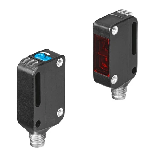
Festo 8075665 Through-Beam Sensor Set, Red LED, IO-Link

Original price was: USD 238.16.Current price is: USD 204.88.

Transmitter and receiver with 0–12 m range, 1000 Hz switching, push-pull output, three-pin M8 connections and IP65/IP67/IP69K protection.

SKU Festo-8075665 Category
Festo Optical Sensors

Festo SOOE-TB-R-PNLK-T Through-Beam Sensor Set

BrandFesto
Model IdentifierSOOE-TB-R-PNLK-T
Official Part Number8075665

Technical Overview

The Festo SOOE-TB-R-PNLK-T is a red-LED through-beam sensor set supplied with both transmitter and receiver. Its optoelectronic detection range is 0–12000 mm, with a maximum light spot of 65 mm at 1000 mm. The receiver provides a push-pull switching output rated up to 100 mA and a maximum switching frequency of 1000 Hz. IO-Link Device V1.1 supports COM2 communication, switching-signal and stability-alarm data, and timer configuration. Three-pin A-coded M8 connections supply the 10–30 V DC devices. Through-hole mounting for M3 screws, IP65/IP67/IP69K protection and a −40 to +60 °C ambient range characterize the installation interfaces and environmental ratings.

Red-LED transmitter/receiver through-beam set with 0–12 m range, 1000 Hz push-pull switching, IO-Link and three-pin M8 connections.

Key Features

  • Transmitter and receiver included under part number 8075665
  • Red-LED through-beam optoelectronic detection
  • 0–12000 mm operating distance
  • 65 mm maximum light spot at 1000 mm
  • 1000 Hz maximum switching frequency and 100 mA maximum output current
  • Push-pull output with switchable PNP dark/NPN light switching
  • IO-Link Device V1.1, COM2 at 38.4 kBaud and 2.3 ms minimum cycle time
  • IO-Link switching-signal and stability-alarm input data
  • 10–30 V DC operation through three-pin A-coded M8 connections
  • IP65/IP67/IP69K protection and −40 to +60 °C ambient range

Detect beam interruption across a 0–12 m range with a supplied red-LED transmitter/receiver set and IO-Link switching and stability data.

Technical Specification Matrix

ParameterValue
DesignBlock design
Conforms to standardEN 60947-5-2
ApprovalRCM; c UL us - Listed (Oil)
CE mark (see declaration of conformity)To EU EMC Directive; In accordance with EU RoHS Directive
UKCA marking (see declaration of conformity)To UK instructions for EMC; To UK RoHS instructions
Certificate issuing authorityUL E232949
Note on materialsRoHS compliant
Measuring principleOptoelectronic
Detection methodThrough-beam sensor; Transmitter; Receiver
Type of lightRed; LED
Max. light spot65 mm with 1000 mm
Operating distance0 mm...12000 mm
Ambient temperature-40 °C...60 °C
Switching outputPush-pull
Switching element functionSwitchable; PNP dark switching; NPN light switching
Max. switching frequency1000 Hz
Max. output current100 mA
Voltage drop0 V...1.5 V
Timer functionVia IO-Link®
Short circuit current ratingPulsed
ProtocolIO-Link®
IO-Link, Protocol versionDevice V 1.1
IO-Link, communication modeCOM2 (38.4 kBaud)
IO-Link, SIO-Mode supportYes
IO-Link, Port classA
IO-Link, Process data length OUT1 bit (Emitter); 2 bit (Receiver)
IO-Link, Process data content OUT1 bit (emitter disable); 1 bit (Hold)
IO-Link, Process data length IN2 bit (Receiver)
IO-Link, Process data content IN1 bit (Stability Alarm); 1 bit SSC (Switching Signal)
IO-Link, Min. cycle time2.3 ms
IO-Link, Data storage required2 KB
Operational voltage range DC10 V...30 V
Residual ripple10%
No-load supply current14 mA
Reverse polarity protectionFor all electrical connections
Electrical connection 1, connection typePlug
Electrical connection 1, connector systemM8x1, A-coded, to EN 61076-2-104
Electrical connection 1, number of connections/cores3
Electrical connection 1, type of mountingScrew-type lock
Material electrical contactGold-plated brass
Type of mountingVia through-hole for M3 screw
Tightening torque0.8 Nm
Mounting positionAny
Physical Weight (kg)0.02
Material housingMakrolon®; PLEXIGLAS®
Ready status indicationGreen LED
Switching status indicationYellow LED
Function reserve indicationFlashing yellow LED
Setting optionsIO-Link®; Poti; Teach-in
Degree of protectionIP65; IP67; IP69K
Insulation voltage500 V
Immunity to surge1 kV
Corrosion resistance class CRC1 - Low corrosion stress
LABS (PWIS) conformityVDMA24364 zone III
Pollution degree3
Scope of deliveryThrough-beam sensor transmitter and receiver

Industrial Applications

1. Counting Separated Opaque Components

A conveyor presents separated opaque components through a defined optical path. The opposed transmitter and receiver detect interruption of the red-LED beam, and the receiver's push-pull output supplies a switching signal to the controller. The 1000 Hz maximum component switching frequency characterizes the sensor response, while the 0–12 m operating range supports arranging the two devices across the conveyor width.

Problem Solved

Beam interruption converts passage of a suitable opaque component into an electrical switching event, providing a non-contact signal for the controller's counting sequence.

Through-beam detection 1000 Hz maximum Push-pull output

2. Persistent Obstruction Monitoring at a Transfer Opening

A transfer chute needs to distinguish a briefly passing workpiece from a beam path that remains obstructed. The through-beam set supplies the switching signal, and its timer function can be configured through IO-Link for the applicable sensor behavior. Mounting the transmitter and receiver across the opening provides a defined optical path, with the 0–12000 mm range describing the supported separation rather than an assumed chute geometry.

Problem Solved

The switching signal and configurable timer function provide the sensor-level inputs for identifying persistent beam interruption, supporting a controller response to a blocked transfer path.

IO-Link timer 0–12000 mm Beam interruption

3. Optical Signal Stability Monitoring

A machine needs more information than the presence signal alone when optical alignment or transmission conditions deteriorate. This receiver makes a stability-alarm bit and switching-signal bit available through IO-Link process data. Local green and yellow indicators also display readiness and switching behavior, with flashing yellow indication for function reserve, giving maintenance personnel documented sensor information at the device and through the connected control system.

Problem Solved

The separate stability information supplements ordinary switching events, giving the control and maintenance workflow a documented indication of optical signal condition rather than only an object-detection result.

Stability alarm IO-Link COM2 Function reserve indication
Select your currency