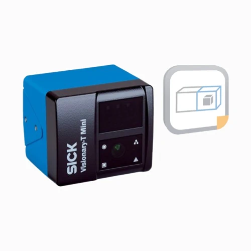
| Technology | 3D snapshot time-of-flight |
| Sensor resolution | 512 × 424 pixels |
| Programmability | Programmable, configurable and pre-calibrated |
| Application software | 3D Object Detection Core; installed SensorApp for configurable collision avoidance on mobile platforms; data processed within device; app can be removed |
| License | Core device license bound to hardware ID; issued without a time limit |
| Core firmware compatibility | SICK release notes specify firmware 3.15.3 for the 3D Object Detection app; firmware 4.3.1 does not support that app and cannot be downgraded to older firmware |
| Working range | ≤9 m depending on infrared remission; reliability is lower beyond 9 m and individual pixels/groups may return erroneous values |
| Field of view | 70° × 60° |
| Angular resolution | 0.14° × 0.14° |
| Illumination | Integrated invisible infrared laser, 855 nm ±5 nm |
| Laser class | Class 1; P0 <17 mW, pulse t <25 ns; IEC 60825-1:2014 and EN 60825-1:2014+A11:2021; CDRH deviation per Laser Notice 56, May 8, 2019 |
| Manufacturer task areas | Standard-object detection; dimension/contour/volume measurement; guiding; 3D position determination; application-specific software required |
| Processor | 1.8 GHz; four ARM Cortex cores; part of resources used internally; CPU load visible in SICK AppStudio |
| Acquisition frame rate | ≤30 fps |
| Exposure time | ≤10 ms |
| Core response time | ≤100 ms for default four simultaneous 3D fields with 2 × 2 pixel binning |
| Switch-on delay | Approximately 20 s on restart; firmware release notes specify longer warm-up at internal temperatures below 0 °C |
| Camera coexistence mode | Automatic |
| Measurement accuracy and repeatability | Typical values in central 80% of detection area, room temperature, no ambient light, 25 fps; radial distance; see qualified reference points |
| Reference values at 1 m radial distance | 90% remission: accuracy ±3 mm, repeatability 1σ ±0.8 mm; 10% remission: accuracy ±3 mm, repeatability 1σ ±1.5 mm; stated reference conditions apply |
| Reference values at 7 m radial distance | 90% remission: accuracy ±10 mm, repeatability 1σ ±5 mm; 10% remission: accuracy ±20 mm, repeatability 1σ ±50 mm; stated reference conditions apply |
| Temperature effect on measurement accuracy | Over the full ambient operating range, degradation up to ±10 mm, typically ±5 mm |
| Detection-area examples | Axial z=1 m: Δx=1.4 m, Δy=1.2 m; z=2 m: 2.8 × 2.3 m; z=6 m: 8.4 × 6.9 m; these are field-of-view dimensions |
| Ethernet | Gigabit Ethernet; TCP/IP and UDP/IP; data application-specific or defined by independently developed applications |
| REST API | Communication and configuration interface |
| Configuration software | SICK AppManager; SICK AppStudio; web interface; telegram interface |
| Digital I/O | Six configurable digital inputs/outputs; ≤100 mA per output; total all outputs <500 mA; voltage drop <2 V at 100 mA; short-circuit protected |
| Power/I/O connector | A-coded M12 eight-pin male |
| Power/I/O pin assignment | 1=24 V supply; 2=DIO3; 3=GND; 4=DIO4; 5=DIO1; 6=DIO5; 7=DIO6; 8=DIO2 |
| Ethernet connector | X-coded M12 eight-pin female |
| Ethernet pin assignment | 1=DA+; 2=DA−; 3=DB+; 4=DB−; 5=DD+; 6=DD−; 7=DC−; 8=DC+ |
| Power supply | 24 V DC, −30%/+25% |
| Power consumption | Typical 12 W without digital I/Os; <8 W in energy-saving mode |
| Peak current | 2 A |
| Protection class | III |
| IP rating | IP65 / IP67 / IP69 |
| Window material | PMMA |
| Housing color | Blue and black |
| Mounting | Four M5 holes 7.5 mm deep; two Ø5H7 fits 7 mm deep; four M5 holes 5.5 mm deep; use manufacturer mounting diagram |
| Indication | Four LEDs for device, application and Ethernet status |
| Operating temperature | Normal −10 to +50 °C; operation from −20 °C after 45-minute warm-up at ≥−10 °C and frame rate >25 fps; lower frame rates possible with lower heat dissipation per manufacturer |
| Camera housing temperature | −10 to +65 °C; provide adequate mechanical heat dissipation/ventilation or appropriate heat sinks |
| Storage temperature | −20 to +80 °C |
| Relative humidity | ≤95% RH, non-condensing |
| Damp heat test | +25 to +55 °C, 95% RH; EN 60068-2-30:2005 |
| Ambient light immunity | ≤50 klx sunlight at 2 m measuring distance |
| Vibration resistance | 5 g, 10–500 Hz; IEC 60068-2-6:2008 and IEC 60068-2-64:2008 |
| Shock resistance | 30 g, 11 ms; IEC 60068-2-27:2008 |
| EMC | IEC 61000-6-4:2018 / EN IEC 61000-6-4:2019; IEC 61000-6-2:2005 / EN 61000-6-2:2005; IEC 61000-6-2:2016 / EN IEC 61000-6-2:2019 |
| Items supplied | Hardware, software and Core software license |
| Physical Weight (kg) | 0.52 |