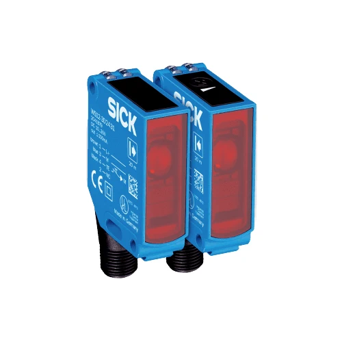
SICK 1041459 WSE12-3P2431 PNP Through-beam Sensor

USD 300.56

WSE12-3P2431 provides 0–15 m through-beam sensing, complementary PNP outputs, ≤330 µs response, M12 four-pin connections and IP66/IP67/IP69K protection.

SKU SICK-1041459 Category
SICK W12-3

SICK WSE12-3P2431 PNP Through-beam Photoelectric Sensor

BrandSICK
Model IdentifierWSE12-3P2431
Official Part Number1041459

Technical Overview

The SICK WSE12-3P2431 detects interruption of a visible red optical path between a WS12-3D2430 sender and WE12-3P2431 receiver. It specifies a 0–15 m sensing range and 0–20 m maximum range, with a 640 nm LED producing a 220 mm light spot at 15 m. A five-turn sensitivity potentiometer supports setup, and complementary PNP outputs provide light/dark switching states for external control. Response is no more than 330 µs with a resistive load, with 1,500 Hz switching at a 1:1 light/dark ratio. The metal housing uses M12 four-pin male connections and PMMA optics, with IP66/IP67/IP69K ratings and two supplied BEF-KH-W12 clamps including screws.

Red-light through-beam sensor with 0–15 m sensing range, complementary PNP outputs, M12 four-pin connections and two supplied BEF-KH-W12 mounting clamps.

Key Features

  • Through-beam detection with separate WS12-3D2430 sender and WE12-3P2431 receiver
  • 0–15 m sensing range; 0–20 m maximum range
  • 640 nm visible red LED; Ø220 mm spot at 15 m; approx. 1.5° dispersion
  • Five-turn sensitivity potentiometer
  • Complementary PNP outputs; light/dark switching
  • ≤330 µs response with resistive load; 1,500 Hz at 1:1 light/dark ratio
  • Sender test input: TE to 0 V switches sender off
  • 10–30 V DC; sender ≤30 mA and receiver ≤15 mA without load
  • M12 four-pin male connections; metal housing and PMMA front screen
  • IP66/IP67/IP69K; two BEF-KH-W12 clamps including screws supplied

Monitor interruption of a separate red-light optical path and provide complementary PNP switching states, with a sender test input for commissioning checks.

Technical Specification Matrix

ParameterValue
Functional principleThrough-beam photoelectric sensor
Individual componentsSender WS12-3D2430, part 2041879; receiver WE12-3P2431, part 2041881
Sensing range0–15 m
Maximum sensing range0–20 m
Light sourceVisible red LED; average service life 100,000 h at +25 °C
Wavelength640 nm
Light spot sizeØ220 mm at 15 m
Angle of dispersionApprox. 1.5°
AdjustmentSensitivity potentiometer, five turns
Switching outputPNP, complementary Q and Q complement
Switching modeLight/dark switching through complementary outputs
Signal voltage HIGH/LOWHIGH > supply voltage −2.5 V; LOW approximately 0 V
Output current≤100 mA
Response time≤330 µs with resistive load
Switching frequency1,500 Hz at 1:1 light/dark ratio
Sender test inputTE to 0 V switches sender off
Power supply10–30 V DC; limit values in short-circuit protected network, maximum 8 A
Ripple<5 Vpp; must remain within supply-voltage limits
Sender current consumption≤30 mA without load
Receiver current consumption≤15 mA without load
Protection classIII
Circuit protectionSupply reverse-polarity protection; interference suppression; output overcurrent and short-circuit protection
ConnectionM12 four-pin male connectors
Sender pin assignmentCD-072: 1 BN=L+; 2 WH=not connected; 3 BU=M; 4 BK=Test
Receiver pin assignmentCD-072: 1 BN=L+; 2 WH=Q complement; 3 BU=M; 4 BK=Q
Housing materialMetal
Front screenPMMA plastic
IP ratingIP66 / IP67 / IP69K
Operating temperature−40 to +60 °C
Storage temperature−40 to +75 °C
MountingØ4.2 mm mounting holes; M4 threaded hole, 4 mm deep
Items suppliedTwo BEF-KH-W12 clamps, including screws
IndicatorsGreen supply-voltage indicator; yellow received-light status
MTTFD826 years
Diagnostic coverageDCavg 0%
Physical Weight (kg)0.12

Industrial Applications

1. Counting separated loads across a conveyor

A conveyor can mount the sender and receiver on opposite sides of an opening so each opaque load interrupts the beam. External counting logic evaluates the complementary PNP signals, with the chosen clear-beam or interrupted-beam state matched to its input logic. Setup checks actual separation, load gaps and transit time against the documented sensing range and switching limits.

Problem Solved

A discrete optical-path reference helps external logic register separated load passages across the conveyor opening, using complementary signals and verified timing for the installed arrangement.

Load counting Complementary PNP Through-beam path

2. Confirming a carrier at a receiving position

A receiving station can arrange the optical path so an opaque carrier blocks the beam at its seated position. The sensitivity potentiometer supports alignment and signal-margin checks, while received-light indication helps verify the clear path during commissioning. External sequencing logic reads the selected complementary output after representative carrier positions and surrounding conditions have been checked.

Problem Solved

A beam-state reference helps external sequencing logic recognize a carrier at the monitored receiving position, with local adjustment and indication supporting the commissioned optical path.

Carrier arrival Received-light state Local adjustment

3. Checking the optical switching response during setup

During commissioning, external test logic can apply 0 V to the sender test input to turn off the emitted beam and observe the resulting receiver output states. The check uses the documented sender and receiver pin assignments and considers response timing. Restoring the test condition and confirming the clear-beam state verifies the local switching response as part of machine setup.

Problem Solved

A controlled sender-off check helps commissioning logic exercise the optical switching path and connected inputs, without treating the ordinary photoelectric sensor as a machine safety function.

Sender test Commissioning Input checks

Select your currency