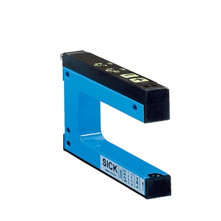
SICK 6028428 WF2-40B410 Infrared Fork Sensor

USD 163.54

WF2-40B410 combines infrared fork sensing, a 2 mm opening, 0.2 mm minimum object detection, 10 kHz switching, PNP/NPN outputs and an M8 connector.

SKU SICK-6028428 Category
SICK WF

SICK WF2-40B410 Infrared Fork Sensor

BrandSICK
Model IdentifierWF2-40B410
Official Part Number6028428

Technical Overview

The SICK WF2-40B410 is an infrared optical fork sensor with a 2 mm opening and 42 mm fork depth. The sender and receiver share one aluminum housing, creating a defined optical path for detecting material entering the fork. Its minimum detectable object is 0.2 mm. Plus/minus buttons set sensitivity, light/dark switching and the key lock, while PNP and NPN outputs provide machine control signals. A response time of no more than 100 µs and 10 kHz switching frequency support repeated object transitions within the documented timing limits. The sensor operates from 10–30 V DC and connects through an M8 four-pin male connector, with IP65 protection.

Infrared fork sensor with 2 mm opening, PNP/NPN outputs, adjustable light/dark switching, M8 four-pin connector and IP65 aluminum housing.

Key Features

  • Infrared LED optical fork sensing
  • 2 mm fork opening; 42 mm fork depth
  • Minimum detectable object 0.2 mm
  • Plus/minus buttons for sensitivity, light/dark switching and key lock
  • PNP and NPN switching outputs
  • Response ≤100 µs; 10 kHz switching
  • Response stability ±20 µs; jitter 40 µs
  • 10–30 V DC supply; 100 ms initialization
  • M8 four-pin male connector
  • IP65 aluminum housing; −20 to +60 °C operation

Use a fixed optical fork path to detect small opaque features, with local sensitivity adjustment and 10 kHz switching.

Technical Specification Matrix

ParameterValue
Functional principleOptical fork sensor
Housing formFork shaped
Fork width2 mm
Fork depth42 mm
Label detectionSupported
Minimum detectable object0.2 mm
AdjustmentPlus/minus buttons: sensitivity, light/dark switching and key lock
Teach-in modeNone specified
Power supply10–30 V DC; reverse-polarity protected; short-circuit-protected network max. 8 A
Residual ripple<10%; remain within supply-voltage tolerance
Current consumption40 mA
Initialization time100 ms
Switching outputPNP and NPN
Switching modeLight/dark switching, selectable via buttons
Switching frequency10 kHz
Response time≤100 µs
Output current100 mA
ConnectionMale connector M8, 4-pin
Circuit protectionSupply reverse-polarity protection; Q short-circuit protection; interference pulse suppression
Protection classIII; reference voltage 50 V DC
Housing materialAluminum
IP ratingIP65
Operating temperature−20 to +60 °C
Storage temperature−30 to +80 °C
Shock resistanceEN 60068-2-27
MTTFD97 years
Diagnostic coverage DCavg0%
UL fileNRKH.E191603
Light sourceInfrared LED
Response stability±20 µs
Jitter40 µs
Ambient light immunity≤10,000 lx
Dimensions L x W x H (cm)5.7 x 1 x 3.2

Industrial Applications

1. Registering opaque labels at a dispensing edge

A labeling machine can guide an opaque label web through the 2 mm opening so the infrared path changes state between label and exposed liner. Sensitivity buttons allow adjustment for the actual materials, and selectable light/dark logic adapts the signal polarity. The 42 mm fork depth defines how far the web can enter the housing.

Problem Solved

A repeatable label-boundary signal gives the machine controller a registration input for positioning the web, supporting coordinated dispensing after the actual liner and label contrast are qualified.

Label detection Infrared Adjustable sensitivity

2. Counting small opaque components

A feeder can guide separated opaque components through the fixed optical path and count each interruption. The stated 0.2 mm minimum detectable object supports small features, while 10 kHz switching and response of no more than 100 µs define the available timing. The component spacing and travel speed must allow distinct transitions.

Problem Solved

Each separated passage creates a contactless event for the machine counter, giving a quantity input without a mechanical feeler touching the moving parts along the feed path.

0.2 mm MDO 10 kHz ≤100 µs

3. Checking opaque strip continuity

A strip feeder can route material through the 2 mm fork opening so an intact strip normally blocks the infrared path. A break or runout restores received light and changes the selected light/dark output state. The M8 four-pin connection carries the signal to compatible controls, and IP65 protection supports machine mounting.

Problem Solved

A sustained change of optical state identifies missing material at the monitored point, allowing the controller to coordinate the feed sequence after detecting a strip break or runout.

Light/dark switching M8 connector Material continuity

Select your currency