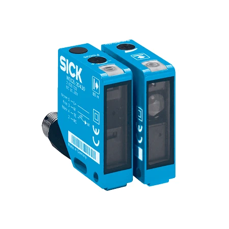
SICK 1047960 WS/WE12L-2P431 Laser Through-beam Sensor Set

USD 105.82

WS/WE12L-2P431 offers a 0–80 m maximum range, class 1 laser, complementary PNP outputs, ≤500 µs response and M12 four-pin connections.

SKU SICK-1047960 Category
SICK W12-2 Laser

SICK WS/WE12L-2P431 Laser Through-beam Sensor Set

BrandSICK
Model IdentifierWS/WE12L-2P431
Official Part Number1047960

Technical Overview

The SICK WS/WE12L-2P431 is a laser through-beam photoelectric sensor set with a separate sender and receiver that detect interruption of their aligned light path. Its specified maximum sensing range is 0–80 m. A visible 650 nm class 1 laser produces a typical Ø150 mm at 60 m spot; a sender focus control and receiver sensitivity potentiometer support setup. Complementary PNP outputs provide process signals to external machine control. Response is ≤500 µs under resistive load, with 1,000 Hz operation at a 1:1 light/dark ratio. Both metal housings use PMMA front screens, IP67/IP69K protection and M12 four-pin connectors. The electronics operate from 10–30 V DC, with separate no-load current limits for sender and receiver.

Laser through-beam sender/receiver set with 0–80 m maximum range, class 1 laser, complementary PNP signals and M12 four-pin connectors.

Key Features

  • Laser through-beam sensing with separate sender and receiver
  • 0–80 m maximum sensing range
  • 650 nm visible red class 1 laser; typical Ø150 mm at 60 m
  • Sender focal adjustment and receiver sensitivity potentiometer
  • Complementary PNP switching outputs, ≤100 mA
  • ≤500 µs response with resistive load; 1,000 Hz at 1:1 light/dark ratio
  • M12 four-pin connectors; sender test connection on pin 4
  • Metal housings with PMMA front screens; IP67/IP69K
  • 10–30 V DC; sender ≤45 mA and receiver ≤15 mA without load
  • Two BEF-KH-W12 clamps with screws included

Detect interruption of an aligned laser beam between separate sender and receiver heads and provide complementary signals to external process control.

Technical Specification Matrix

ParameterValue
Functional principleThrough-beam photoelectric sensor; separate sender and receiver
Set components2051073 WS12L-2D431; 2051074 WE12L-2P431
Maximum sensing range0–80 m
Light sourceVisible red laser
Wavelength650 nm
Laser class1
Light spot sizeTypically Ø150 mm at 60 m
Laser service lifeAverage 50,000 h at ambient +25 °C
Pulse duration4 µs
Maximum laser pulse power<5.0 mW
AdjustmentReceiver sensitivity potentiometer; sender focal adjustment
Digital outputPNP; maximum output current ≤100 mA
Output functionComplementary Q and /Q
Response time≤500 µs with resistive load
Switching frequency1,000 Hz at 1:1 light/dark ratio
Pin assignmentSender: 1 BN=L+, 3 BU=M, 4 BK=Test; receiver: 1 BN=L+, 3 BU=M, 4 BK=Q, 2 WH=/Q (CD-077)
Sender test connectionTest input on sender pin 4 / black wire
Power supply10–30 V DC; operate in short-circuit protected supply network, maximum 8 A
Sender current consumption≤45 mA without load
Receiver current consumption≤15 mA without load
Residual ripple<5 Vpp; remain within supply limits
Protection classIII
Circuit protectionA: supply reverse-polarity protection; C: interference suppression; D: outputs protected against overcurrent and short circuits
Housing designRectangular
Housing materialMetal
Front screenPMMA plastic
ConnectionMale M12 four-pin connectors
Mounting provisionsM4 threaded hole, 4 mm depth; Ø4.2 mm mounting hole
Items suppliedTwo BEF-KH-W12 clamps, including screws
IP ratingIP67/IP69K
Operating temperature−10 to +50 °C
Storage temperature−25 to +75 °C
MTTFD440 years
DCavg0%
Physical Weight (kg)0.26

Industrial Applications

1. Counting separated opaque products

A conveyor can align the sender and receiver across the path of separated opaque products. Each product interrupts the direct laser beam and changes the complementary signals for external counting logic. The installed separation stays within the 0–80 m maximum range; commissioning checks actual beam coverage, product size, spacing and clear intervals against the optical geometry and switching requirements.

Problem Solved

Direct-beam interruption gives external counting logic a product-passage reference, helping track separated conveyor loads without depending on light reflected from each changing product surface finish.

Opaque products Direct laser beam Complementary signals

2. Monitoring an opaque web for loss of material

A feeder can place an opaque web between the aligned sender and receiver so normal material blocks the direct beam. A break exposes the receiver and changes the switching state for external feeder control. Installation verifies web width, flutter tolerance and sufficient beam interruption at the actual operating distance, using the typical Ø150 mm at 60 m as a reference rather than a guaranteed minimum detectable web width.

Problem Solved

A blocked-to-clear direct-beam transition supplies external feeder control with a possible material-loss indication, helping recognize a break before downstream equipment continues without the expected opaque feed.

Web continuity Beam interruption External feeder control

3. Recognizing occupancy at a transfer point

A transfer station can mount the sender and receiver on opposite sides of an expected load position. A load remaining in the beam maintains the interrupted condition, which external control evaluates over time using its own dwell timer. The complementary signals provide alternative process states for the control circuit, while head alignment and actual load coverage are checked during commissioning.

Problem Solved

Sustained beam interruption provides external transfer control with an occupied-position reference, helping coordinate upstream release when a load remains in place instead of clearing after its normal transfer cycle.

Transfer occupancy External dwell timing Aligned sender/receiver

Select your currency