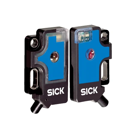
SICK 6030570 PNP Through-beam Photoelectric Sensor

USD 141.44

WS/WE2F-F210 provides 0–0.4 m through-beam sensing, PNP dark switching, 1,000 Hz operation and 200 mm M8 cables in IP67 PC housings.

SKU SICK-6030570 Category
SICK W2 Flat

SICK WS/WE2F-F210 Through-beam Photoelectric Sensor

BrandSICK
Model IdentifierWS/WE2F-F210
Official Part Number6030570

Technical Overview

The SICK WS/WE2F-F210 is a miniature through-beam photoelectric sensor with separate sender and receiver units. The optical path spans 0–0.4 m sensing distance, with 0–0.5 m maximum range. Its 660 nm visible red LED produces a 10 mm spot at 100 mm. The receiver provides PNP dark switching for external machine control, with response up to 0.5 ms under resistive load and 1,000 Hz operation at a 1:1 light/dark ratio. No sensitivity adjustment is provided. PC housings and optics, 200 mm PVC cables with M8 three-pin connectors and IP67 protection support compact installations with access to both sides of the detection path.

Compact through-beam sensor with 0–0.4 m sensing range, PNP dark switching, 660 nm LED illumination and 200 mm PVC cables with M8 three-pin connectors.

Key Features

  • Through-beam sensing with separate sender and receiver
  • 0–0.4 m sensing; 0–0.5 m maximum range
  • 660 nm visible red LED; Ø10 mm spot at 100 mm
  • No sensitivity adjustment
  • PNP dark-switching output; maximum current ≤50 mA
  • ≤0.5 ms response with resistive load; 1,000 Hz at 1:1 light/dark ratio
  • 12–24 V DC supply with ±10% tolerance
  • 200 mm PVC cable with M8 three-pin connector; Ø2.4 mm cable
  • PC housing and PC optics; mounting holes Ø2.1 mm
  • IP67 protection; −20 to +55 °C operation

Detect beam interruption across a compact machine opening using separate sender and receiver units and a dedicated switching output.

Technical Specification Matrix

ParameterValue
Functional principleThrough-beam photoelectric sensor; separate sender and receiver
Sensing range0–0.4 m
Maximum sensing range0–0.5 m
Light sourceVisible red LED
Wavelength660 nm
LED service lifeAverage 100,000 h at +25 °C
AdjustmentNone
Digital outputPNP switching output; maximum output current ≤50 mA
Switching modeDark switching
Output signal levelsApprox. VS −1.8 V / 0 V for PNP HIGH/LOW
Response time≤0.5 ms signal transit time with resistive load
Switching frequency1,000 Hz at 1:1 light/dark ratio
Power supply12–24 V DC, ±10% tolerance
Residual ripple<5 Vpp; remain within supply tolerances
Connection200 mm PVC cable with M8 three-pin connector; do not bend cable below 0 °C
Cable diameterØ2.4 mm
Pin assignmentSender: 1 BN=L+, 3 BU=M, 4 BK not connected; receiver: 1 BN=L+, 3 BU=M, 4 BK=Q (CD-051)
Circuit protectionA: supply connections reverse-polarity protected; C: interference suppression; D: outputs overcurrent and short-circuit protected
Housing materialPC plastic
Optics materialPC plastic
Mounting provisionsMounting holes Ø2.1 mm
IP ratingIP67
Operating temperature−20 to +55 °C
Storage temperature−40 to +75 °C
MTTFD988 years
DCavg0%
Light spot sizeØ10 mm at 100 mm

Industrial Applications

1. Counting separated opaque parts at a small chute

A small-parts chute can place the sender and receiver on opposite sides of a clear opening within the 0–0.4 m sensing range. Each separated opaque part interrupts the beam as it falls. External counting logic evaluates the PNP output, with the part profile, spacing and transit speed checked against the beam geometry and switching limits.

Problem Solved

A discrete passage reference helps external counting logic register separated parts at a narrow chute without depending on light returned from each part surface.

Small-parts chute Beam interruption External counting

2. Confirming a carrier at a compact transfer stop

A transfer station can align the sender and receiver across an opaque feature of a carrier at its seated position. The 0–0.4 m sensing range supports a short optical crossing, while the separate receiver supplies the switching state. External transfer control samples that state before coordinating release, after the actual carrier geometry and seated tolerance have been checked.

Problem Solved

A carrier-arrival reference helps external transfer control coordinate a staged handoff, using an interrupted optical path to distinguish the seated carrier from an empty stop.

Carrier arrival Transfer stop Separate receiver

3. Monitoring an opaque strip edge at a guide

A strip guide can position the sender and receiver across a defined edge location so that an opaque strip normally interrupts the beam. Lateral movement that uncovers the path changes the receiver output. External process control evaluates that condition as a discrete edge-presence reference, with strip opacity, flutter and actual alignment checked during installation.

Problem Solved

A discrete strip-edge reference helps external process control recognize an uncovered guide position without requiring a reflective target surface or a reflector behind the moving strip.

Opaque strip Edge presence Through-beam optics

Select your currency