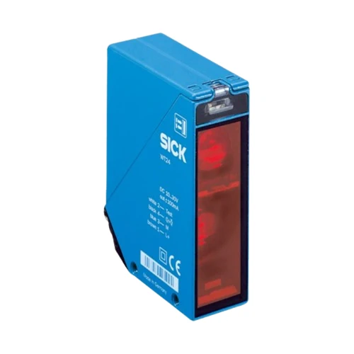
SICK 1016933 WT24-2B410 Selectable PNP/NPN Photoelectric Sensor

USD 343.98

100–2,500 mm reference-white background-suppression sensing, infrared LED, sender-off test input and M12 four-pin connection in an IP69K zinc housing.

SKU SICK-1016933 Category
SICK W24-2

SICK WT24-2B410 Background Suppression Photoelectric Sensor

BrandSICK
Model IdentifierWT24-2B410
Official Part Number1016933

Technical Overview

The SICK WT24-2B410 is an infrared LED photoelectric proximity sensor with background suppression and a 100–2,500 mm sensing range on 90% remission reference white. A potentiometer adjusts the working distance, while separate selectors choose PNP or NPN output and light or dark switching. Its test input switches the sender off when TE is connected to 0 V, supporting a controlled signal check by external machine logic. Response is no more than 500 µs with resistive load, with 1,000 Hz switching at a 1:1 light/dark ratio. The 10–30 V DC unit has a zinc die-cast housing, PMMA optics, IP69K protection and a four-pin M12 connector.

Infrared background-suppression sensor with 100–2,500 mm reference-white sensing, selectable PNP/NPN and light/dark switching, sender-off test input and M12 connector.

Key Features

  • Photoelectric proximity sensing with background suppression
  • 100–2,500 mm sensing and maximum range on 90% remission reference white
  • Infrared LED; 80 mm spot diameter at 2,500 mm
  • Sensing-range potentiometer; separate PNP/NPN and light/dark selectors
  • ≤500 µs response with resistive load; 1,000 Hz at 1:1 light/dark ratio
  • Sender-off test input: TE to 0 V
  • 10–30 V DC; 50 mA without load; output current ≤100 mA
  • Four-pin M12 male connector; M5 mounting holes
  • Zinc die-cast housing and PMMA optics; IP69K
  • Operating temperature −40 to +60 °C; alignment sight and LED signal-strength indicator

Set the target distance and PNP/NPN signal behavior locally, with a sender-off test input available for a controlled optical signal check.

Technical Specification Matrix

ParameterValue
Functional principlePhotoelectric proximity sensor with background suppression
Sensing range100–2,500 mm on 90% remission reference white, DIN 5033
Maximum sensing range100–2,500 mm on 90% remission reference white, DIN 5033
Light sourceInfrared LED
Light spot sizeØ80 mm at 2,500 mm
LED service lifeAverage 100,000 h at TU = +25 °C
AdjustmentSensing-range potentiometer
Digital outputSelectable PNP or NPN; current ≤100 mA
Switching modeSelectable light or dark switching
SelectorsSeparate PNP/NPN selector and light/dark selector
Response time≤500 µs signal transit time with resistive load
Switching frequency1,000 Hz at 1:1 light/dark ratio
Power supply10–30 V DC; limit values with short-circuit-protected network, max. 8 A
Residual ripple<5 Vpp; remain within supply tolerances
Current consumption50 mA without load
Test inputTE to 0 V switches sender off
ConnectionM12 four-pin male connector
Pin assignmentCD-117: 1 BN=L+; 2 WH=Test; 3 BU=M; 4 BK=Q/Q̅ according to selected mode
Circuit protectionA: supply reverse-polarity protection; C: interference suppression; D: output overcurrent and short-circuit protection
Protection classII; reference voltage 50 V DC
Housing designRectangular
Housing materialZinc die-cast metal
Optics materialPMMA plastic
IP ratingIP69K
MountingM5 threaded mounting hole, 6 mm deep; M5 threaded through-hole; see exact drawing
Connector orientationConnector arrangement rotatable by 90°; follow manufacturer drawing
Indicators and alignmentAlignment sight; LED signal-strength indicator
Operating temperature−40 to +60 °C
Storage temperature−40 to +75 °C
MTTFD456 years
DCavg0%
UL filesNRKH.E181493 and NRKH7.E181493
Physical Weight (kg)0.33

Industrial Applications

1. Counting separated cartons beside a conveyor

A conveyor can present separated opaque cartons within the sensor’s adjusted working distance while a farther machine surface remains behind them. Background suppression establishes the target zone, and local selectors match PNP or NPN and light/dark behavior to the external counter. Setup checks actual carton reflectance, spacing and speed against the reference-target limits and response specifications.

Problem Solved

A carton-passage reference helps external counting logic track separated loads from one mounting side, using an adjusted target zone and selectable electrical output behavior.

Carton counting Background suppression PNP/NPN selection

2. Checking a load on a presented carrier

A handling station can present a carrier so its expected load lies within the sensor’s adjusted target zone and the unloaded carrier surface lies farther away. The potentiometer establishes that separation using representative loads and empty carriers. External inspection logic samples the switching state after presentation, with setup checking placement tolerance and the shorter limits for darker surfaces.

Problem Solved

A load-present reference helps external inspection logic distinguish a loaded carrier from an empty presentation, supporting an omitted-load check before the next handling operation.

Load presence Carrier inspection Range adjustment

3. Checking a transfer sensor through its test input

A transfer station can use the sensor’s normal switching state to monitor an opaque carrier, then request a controlled sender-off check when the station permits it. External control logic applies TE to 0 V and observes the resulting signal change. The PNP/NPN and light/dark selectors establish the expected electrical behavior for that check without treating it as a safety function.

Problem Solved

A controlled sender-off condition gives external maintenance logic a repeatable way to compare the sensor signal with an expected optical interruption, supporting troubleshooting at the transfer station.

Sender-off test Transfer monitoring Selectable output

Select your currency