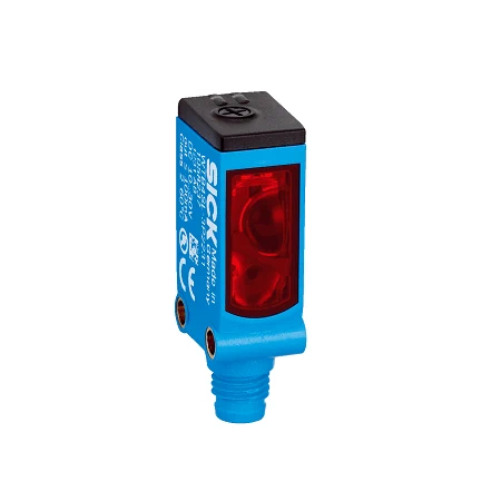
SICK 1058242 WTB4SL-3N1161 NPN Laser Proximity Sensor

USD 326.04

WTB4SL-3N1161 offers 25–300 mm white-target background suppression, a 650 nm Class 1 laser, NPN outputs and a 2 m PVC cable.

SKU SICK-1058242 Category
SICK W4SL-3

SICK WTB4SL-3N1161 Laser Background-suppression Sensor

BrandSICK
Model IdentifierWTB4SL-3N1161
Official Part Number1058242

Technical Overview

The SICK WTB4SL-3N1161 is a slim laser photoelectric proximity sensor with background suppression for small-object detection. It evaluates target-reflected light from one mounting side, with a 25–300 mm sensing and maximum range specified for a white target at 90% remission. A 650 nm visible red Class 1 laser produces a typical 1 mm spot at 170 mm. Sensitivity is set using a five-turn potentiometer. Complementary NPN outputs provide light/dark switching signals to external machine control. Response is ≤0.5 ms under resistive load, with 1,000 Hz operation at a 1:1 light/dark ratio. The Novodur plastic housing uses a PMMA front screen, M3 threaded mounting holes, IP66/IP67 protection and a 2 m four-wire PVC cable.

Laser background-suppression sensor with 25–300 mm white-target range, Class 1 laser, five-turn potentiometer and complementary NPN outputs.

Key Features

  • Laser photoelectric proximity sensing with background suppression
  • 25–300 mm sensing and maximum range on 90% remission white
  • 650 nm visible red Class 1 laser; typical Ø1 mm spot at 170 mm
  • Five-turn potentiometer for sensing-range adjustment
  • Complementary NPN light/dark switching outputs, ≤100 mA
  • ≤0.5 ms response with resistive load; 1,000 Hz at 1:1 light/dark ratio
  • 10–30 V DC; 30 mA without load
  • 2 m four-wire PVC cable; M3 threaded mounting holes
  • Novodur housing, PMMA front screen and IP66/IP67
  • Standard −10 to +50 °C operation; extended operation subject to conditions

Align a small laser spot on the intended target feature and use one-sided background-suppression detection for external component or position checks.

Technical Specification Matrix

ParameterValue
Functional principleLaser photoelectric proximity sensing with background suppression
Sensing range25–300 mm on 90% remission standard white target, DIN 5033
Maximum sensing range25–300 mm on 90% remission standard white target, DIN 5033
Light sourceVisible red laser
Wavelength650 nm
Laser class1; EN 60825-1:2014, IEC 60825-1:2014 / CDRH 21 CFR 1040.10 and 1040.11
Light spot sizeTypically Ø1 mm at 170 mm
Laser service lifeAverage 50,000 h at ambient +25 °C
AdjustmentFive-turn potentiometer
Special applicationDetecting small objects
Digital outputComplementary NPN outputs; maximum output current ≤100 mA
Switching modeLight/dark switching; Q is light switching
Pin assignmentBN=L+; BU=M; BK=Q; WH=/Q (CD-094)
Response time≤0.5 ms signal transit time with resistive load
Switching frequency1,000 Hz at 1:1 light/dark ratio
Power supply10–30 V DC; operate in short-circuit protected supply network, maximum 8 A
Current consumption30 mA without load
Residual ripple<5 Vpp; remain within supply tolerances
Protection classIII
Circuit protectionA: supply reverse-polarity protection; B: inputs and output reverse-polarity protection; C: interference suppression
Housing designSlim, rectangular
Housing materialNovodur plastic
Front screenPMMA plastic
Connection2 m four-wire PVC cable; do not bend below 0 °C
Mounting provisionsM3 threaded mounting holes
IP ratingIP66/IP67
Operating temperatureStandard −10 to +50 °C
Extended operating temperature−30 to +55 °C, subject to cold-start and high-temperature conditions
Extended operation conditionsAt ambient ≥50 °C: maximum supply 24 V and maximum load current 50 mA. Below −10 °C, operation requires starting above −10 °C, then cooling with uninterrupted supply; switching on below −10 °C is not permitted.
Storage temperature−30 to +70 °C
MTTFD417 years, EN ISO 13849-1; Parts-Count calculation
DCavg0%
Physical Weight (kg)0.1
Conductor cross-section0.14 mm²

Industrial Applications

1. Counting separated small opaque components

A feeder can mount the sensor beside an adjusted detection path of separated opaque components, using reflected laser light from one side. The typical 1 mm spot at 170 mm helps align detection with the intended feature. Setup verifies actual target finish, orientation and background spacing; the 25–300 mm range is specified for a 90% remission white reference target. External counting logic checks part gaps against the 1,000 Hz switching specification at a 1:1 light/dark ratio.

Problem Solved

A component-passage reference helps external counting logic track separated parts where one-sided mounting is practical, reducing dependence on a second device or reflector across the feeder after actual targets have been checked.

Small components One-sided laser detection External counting

2. Confirming a narrow carrier feature at a transfer

A transfer can mount the sensor beside an opaque carrier feature that defines the seated position. The five-turn potentiometer sets the sensing position using representative carriers and nearby background conditions. External transfer logic evaluates the complementary NPN states after testing actual feature finish, position tolerances and the separation between the carrier and background throughout the expected mechanical variation.

Problem Solved

A local carrier-position reference helps external transfer control recognize arrival at the intended location, supporting coordinated upstream release when a narrow mechanical feature defines the required seated condition.

Carrier feature Background suppression Transfer position

3. Checking an opaque component at an assembly nest

A machine can present an assembly so the expected opaque component occupies the adjusted laser detection position. Setup checks representative complete and missing-component samples, surface finish and surrounding background, then external inspection logic evaluates the switching state at the correct point in the machine sequence. The five-turn potentiometer provides local adjustment, and the complementary NPN states are verified against the expected presentation sequence.

Problem Solved

A component-present reference helps external inspection logic flag an assembly missing the expected part, reducing the chance that a component omission proceeds unnoticed to the next operation.

Assembly component Nest presence External inspection

Select your currency