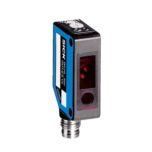
SICK 6033210 WTB8-N1111 NPN Background Suppression Sensor

USD 166.14

WTB8-N1111 offers 20–100 mm reference-white sensing, red LED light, four-turn range adjustment, selectable NPN switching and a 2 m PVC cable.

SKU SICK-6033210 Category
SICK W8

SICK WTB8-N1111 NPN Background Suppression Sensor

BrandSICK
Model IdentifierWTB8-N1111
Official Part Number6033210

Technical Overview

The SICK WTB8-N1111 is a photoelectric proximity sensor with background suppression and an NPN switching output. It specifies 20–100 mm sensing on reference white, with a 5–100 mm maximum range. Its 650 nm red LED produces a 6 mm spot at 100 mm. A four-turn potentiometer adjusts sensing range and a separate rotary switch selects light or dark operation. Response is no more than 0.5 ms with resistive load, with 1,000 Hz switching at a 1:1 light/dark ratio. The sensor uses 10–30 V DC and a 2 m three-wire PVC cable. Its IP67 ABS housing has PMMA optics and M3 threaded mounting holes; a stainless steel BEF-W100-A bracket is supplied.

NPN Background Suppression Sensor with 20–100 mm reference-white sensing, four-turn adjustment, selectable light/dark mode and 2 m PVC cable.

Key Features

  • Photoelectric proximity sensor with background suppression
  • Sensing range: 20–100 mm on 90% remission reference white (DIN 5033)
  • Maximum range: 5–100 mm on 90% remission reference white (DIN 5033)
  • 650 nm visible red LED; Ø6 mm at 100 mm
  • Sensing-range potentiometer, four turns
  • NPN output with selectable light/dark mode
  • ≤0.5 ms response with resistive load; 1,000 Hz at 1:1 light/dark ratio
  • 10–30 V DC; 30 mA without load; ≤100 mA output current
  • 2 m three-wire PVC cable; do not bend below 0 °C
  • IP67; ABS housing; stainless steel BEF-W100-A bracket included

Detect a nearby target while suppressing a more distant background, then connect the selected NPN state to external process control.

Technical Specification Matrix

ParameterValue
Functional principlePhotoelectric proximity sensor with background suppression
Housing designRectangular
Sensing range20–100 mm on 90% remission reference white (DIN 5033)
Maximum sensing range5–100 mm on 90% remission reference white (DIN 5033)
Light sourceVisible red LED
Wavelength650 nm
Light spot sizeØ6 mm at 100 mm
LED service lifeAverage 100,000 h at ambient +25 °C
AdjustmentSensing-range potentiometer, four turns
Switching outputNPN switching output
Switching modeLight/dark switching, selectable via rotary selector (L=light; D=dark)
Signal voltage HIGH/LOWApproximately supply voltage / <1.8 V
Output current≤100 mA
Response time≤0.5 ms with resistive load
Switching frequency1,000 Hz at 1:1 light/dark ratio
Power supply10–30 V DC; limit values in a short-circuit-protected network, maximum 8 A
Ripple±10%; remain within supply tolerances
Current consumption30 mA without load
Connection2 m three-wire PVC cable; do not bend below 0 °C
Electrical protectionSupply reverse-polarity protection; input and output reverse-polarity protection; output overcurrent and short-circuit protection
Housing materialABS
Optics materialPMMA
IP ratingIP67
Operating temperature−25 to +55 °C
Storage temperature−40 to +70 °C
MTTFD1,568 years
Diagnostic coverageDCavg 0%
MountingM3 threaded mounting holes
IndicatorsOrange: switching output active; green: stability indicator
Items suppliedStainless steel mounting bracket BEF-W100-A, material 1.4301/304
Wire assignmentCD-043: BN=L+; BU=M; BK=Q
Physical Weight (kg)0.05

Industrial Applications

1. Confirming a component in an assembly nest

An assembly nest can present a component at a repeatable distance facing the sensor. Background suppression provides a switching condition from one mounting side, while the documented adjustment establishes detection for representative components. External inspection logic samples the output after the component settles. Setup verifies actual target reflectance, placement tolerance and background geometry before accepting the installed detection point.

Problem Solved

A component-present reference helps external inspection logic distinguish an occupied assembly location from an empty nest, using commissioned target geometry and the documented adjustment method.

Assembly presence Background suppression External inspection

2. Counting separated components on a guide

A component guide can move separated parts through the optical sensing point and send switching transitions to external counting electronics. Commissioning establishes the working gap and adjustment using representative materials, including the darkest expected target. Part transit time and gaps are checked against the documented response and switching-frequency conditions before setting the counting logic.

Problem Solved

A discrete optical passage signal helps external counting electronics register separated components, using a commissioned sensing point and timing conditions matched to the actual parts feed.

Part counting Target reflectance Timing checks

3. Confirming a carrier at its transfer stop

A transfer stop can bring a defined carrier surface into the sensor’s working distance. External sequencing logic reads the optical switching state after the carrier reaches its seated position. Setup uses the documented adjustment and verifies actual carrier reflectance, gap tolerance and background geometry, then confirms that the selected light/dark behavior matches the connected process input.

Problem Solved

A seated-carrier condition helps external sequencing logic coordinate the next transfer step, using a checked optical gap and switching behavior for the actual carrier surface.

Carrier arrival Transfer stop Process sequencing

Select your currency